Rebuilding Zenith 32 NDIX Carburetors!
By: Charlie White
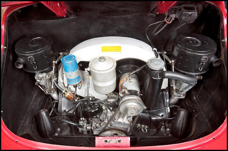
The purpose of this website is to describe in text and pictures, LOTS OF PICTURES, the process of rebuilding a Zenith 32 NDIX carburetor, as found on 356 Porsches from September 1957 through 1965 (spelled out in Factory Service Bulletin #4/58). These two-barrel carburetors are relatively easy to rebuild. It's adjusting and tuning them when they're put back on the engine that is difficult! The emphasis here will be on step-by-step detailed descriptions, with lots of pictures and proper nomenclature so that anyone can rebuild one of these carburetors. Hence, rebuilding a Zenith 32 NDIX carburetor..............!
First some basics.
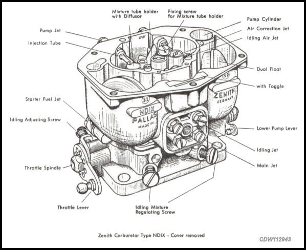 |
Line drawing from the Porsche Factory 356 B/C Workshop Manual. |
 |
Exploded-View Part Diagram from factory 356-B T-5 Parts Book, with part descriptions added. |
Different Versions of Zenith 32 NDIX Carburetors for 356 Porsches!
There are three different versions of
the Zenith 32 NDIX carburetors used on 356
A/B/C Porsches. Below is a table outlining the differences. Before rebuilding
your carburetor, check to see what carburetor you
have. The size of the jets and venturis will tell the tale. Also,
you should be aware that there are
"right
side" carburetors and
"left
side" carburetors. You can tell
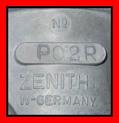
by the number stamped on the right front of the carburetor. There are variations
of these numbers, but here are some examples (P02R, P02L).
The numbers all tell you what carburetor you have
(Normal, Super or 356-C). Since these numbers
vary, it is easier to tell what carburetor you have by looking at the jet
and venturi sizes. One comment often made about these jets and venturies
is if you have a stock engine, or are rebuilding a stock
engine, use the standards set below, unless you are at extreme
elevations either high or low in which case some changes may be
appropriate.
Zenith |
Main Jet | Idle Jet | Idle Air Bleed | Venturi | Pump Jet |
Float Needle |
Air Correction |
| 356 A/B Normal | 115 |
50 |
120 |
24 |
50 |
125 |
230 |
| 356 A/B Super | 130 |
50 |
140 |
28 |
40 |
125 |
220 |
| 356-C | 130 |
55 |
140 |
28 |
40 |
125 |
210 |
Sources: 356-A Factory Workshop Manual Supplement, and 356 B/C Factory Workshop Manual. |
|||||||
If the carburetor you're working on doesn't have the parts with the specs listed above, it has probably been modified for some reason. It is also possible that the prior owner "resized" certain parts, and didn't mark them as such. If in doubt, try and find a new part. The obvious reason for modifying parts is for more performance. Then again the basic carburetor may not be correct for the engine you have. These are areas to check carefully when you're rebuilding your carburetor.
Normally, one would think that the above two diagrams would be sufficient
for anyone to get right into rebuilding a Zenith carburetor. I thought so.
But at least for me, it didn't work out that way.
Frankly, I got confused by all the parts, and by all
the various jets, and floats, and screws. I have a normal hesitation
about working on something like a carburetor. It boils down to
a fear of screwing it up! This greatly impedes taking the carb
apart for fear of breaking something, or losing track of parts when it comes
time to reassemble. So a very orderly process is required for me, together
with lots of pictures to show what it looked like before each time I did
something to it, and a picture afterward to see what it looked like when
I finished, step by step. It occurred to me that there are others out there
like me and that these pictures along with some text would be helpful.
So here
goes! I hope this leads
to a successful rebuild of your Zenith 32 NDIX
Carburetor.
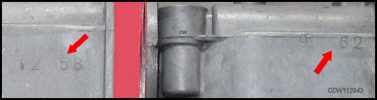
Zenith 32 NDIX Carburetors are DATE STAMPED!
Look on the side of the carburetor for the date stamp which on some carburetors is fairly faint and hard to see. The below two examples are stamped "12 58" and "9 62". Keep in mind, Zenith 32 NDIX Carburetors were used up through 1965 356-C's.
 |
 |
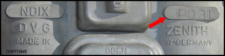
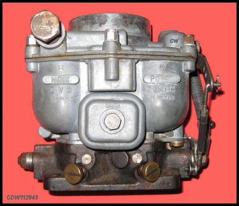
Left Side vs. Right Side Zenith 32 NDIX Carburetors!
 |
 |
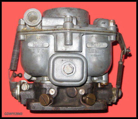
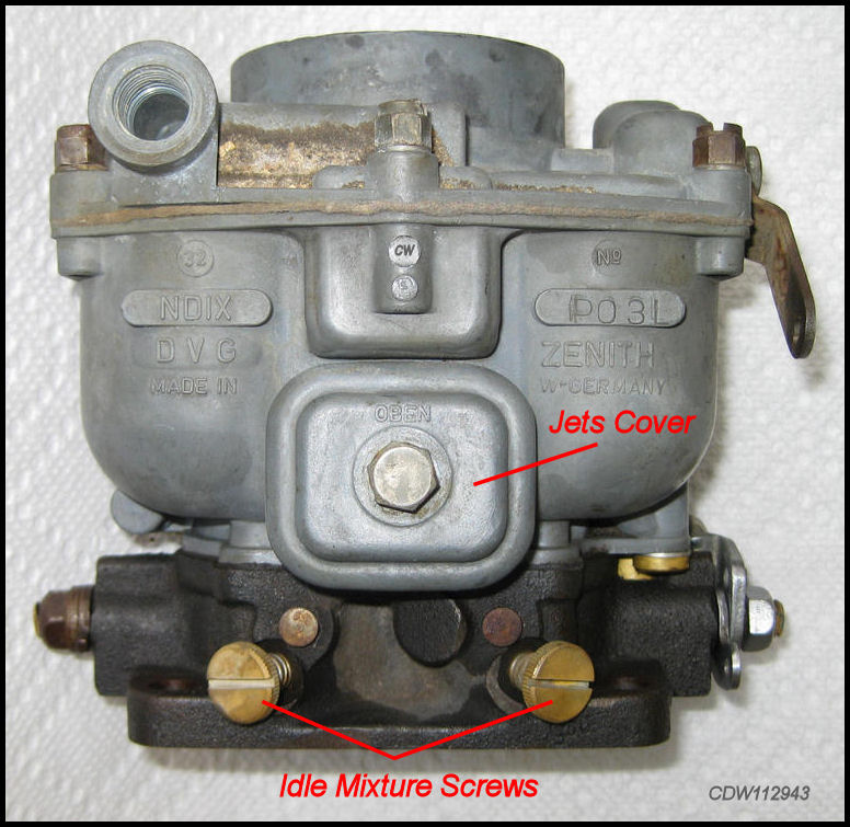
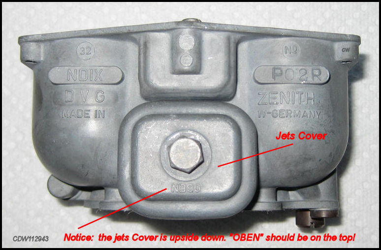
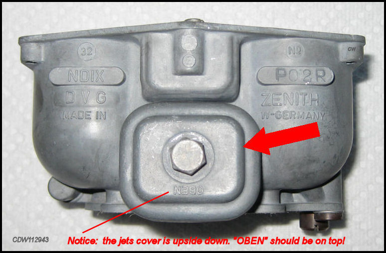
The PO3 Number on the jet cover face of the carburetor indicates L = left side and R = right side. |
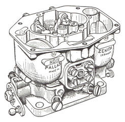
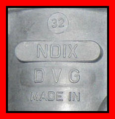
Note on the left side of the
carburetor above the different
names PALLAS
and
DVG.
These are the |
Looking at the Jets Cover side of
the carburetor:
Right
Side
Carburetor...............
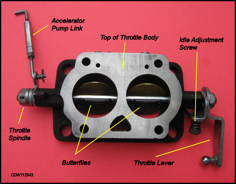
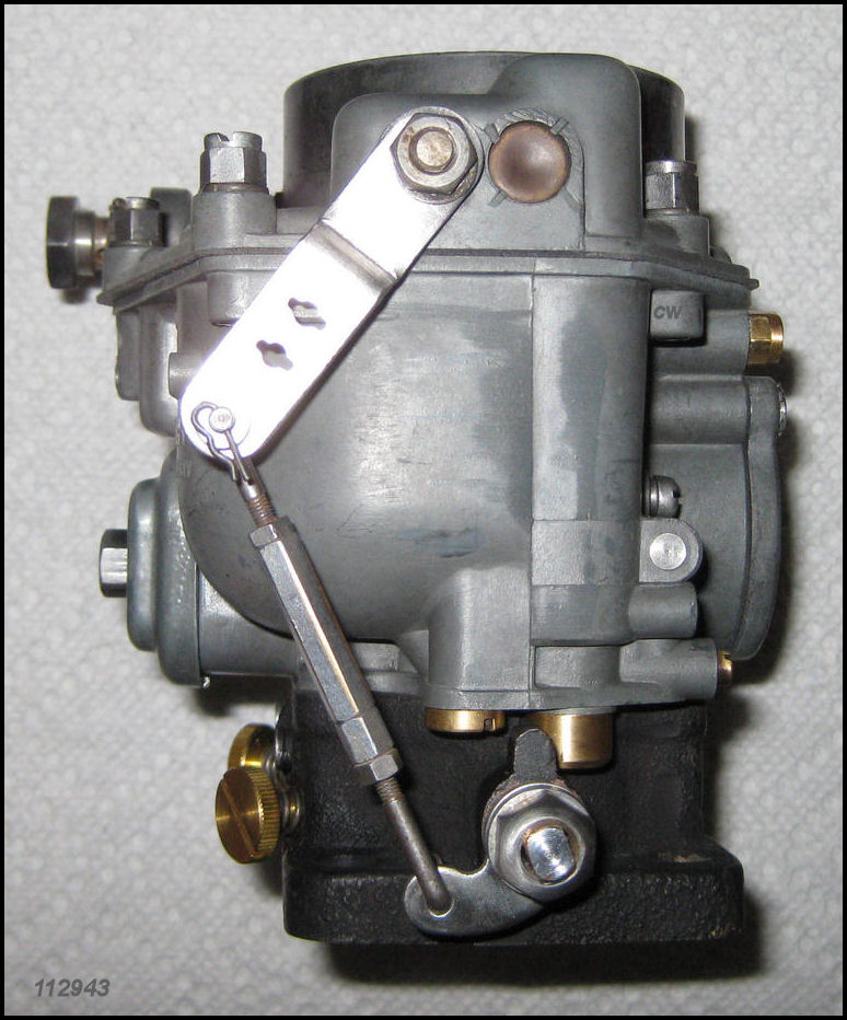
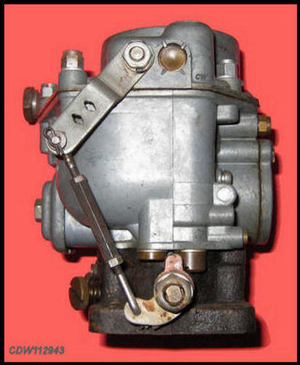
The Throttle Lever, Tension Spring and Idle Adjusting Screw are on the left side of the carburetor, with the Throttle Lever Ball facing the carburetor. The Accelerator Pump Link is on the right side of the carburetor.
Left Side Carburetor...............
The Throttle Lever, Tension Spring, Idle Adjusting Screw and the Accelerator Pump Link are ALL on the right side of the carburetor, with the Throttle Lever Ball facing away from the carburetor.
Look carefully at the exploded-view part diagram above and the images below.
Differences between "Left" and "Right" Zenith 32 NDIX Carburetors on 356 Porsches (before cleaning and rebuilding). |
|
 |
 |
The "Left" Side Carburetor! |
The "Right" Side Carburetor. |
 |
 |
The "Left" Side Carburetor! |
The "Right" Side Carburetor. |
What's in a Rebuild Kit?
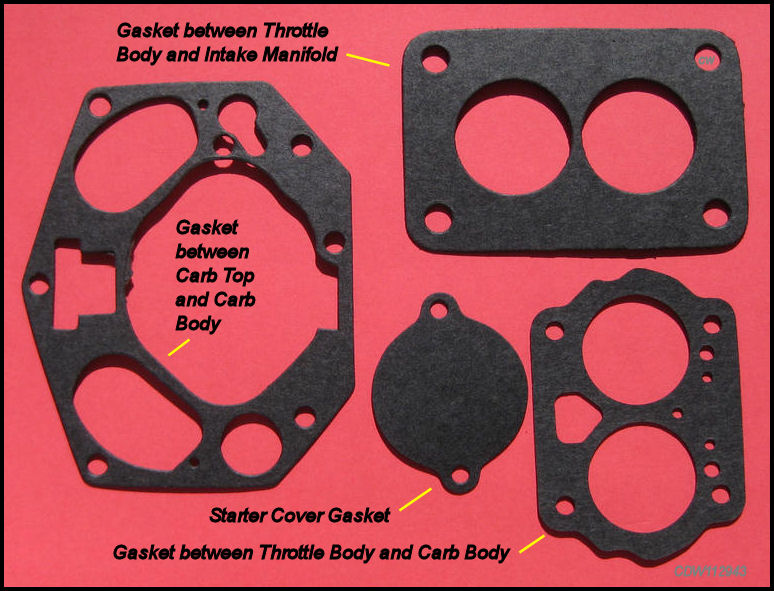
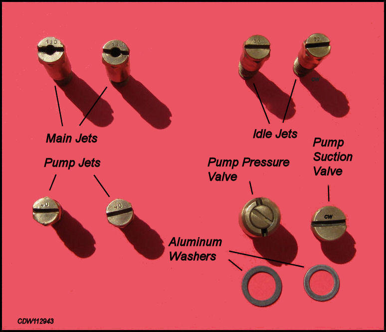
Most rebuild kits come with a part diagram which turns out not to be particularly helpful. One supplier didn't know the answer to the question: "Which washers go where?". It is difficult to tell which washers go where. Some are fabric, some are aluminum, and some are copper. Some are similarly sized. The images below represent a consensus of opinion among knowledgeable carb rebuilders as to what goes where. There is some disagreement and some rebuilders have certain parts made up especially for them. The bottom line is.....look carefully at the parts and washers in your kit and make sure they fit properly.
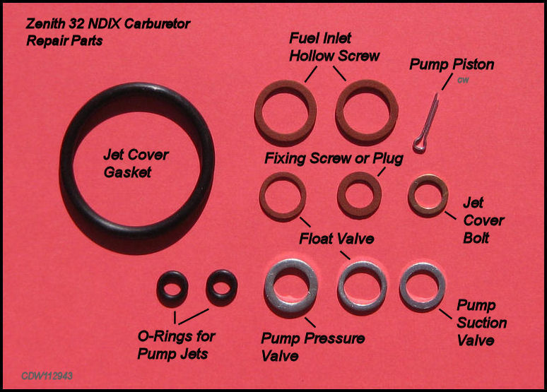 |
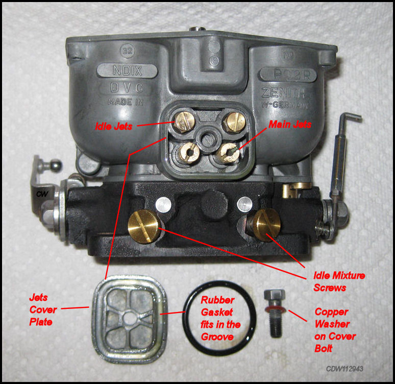
The gasket for the Jet Cover is easy
to figure out. It's the big one. Just be sure to clean out the slot where
this rubber gasket goes before fitting it. The rubber O-Rings for the
Pump Jets can be a hassle to actually mount
on the pump jets. They do stretch, so a little fiddling will get the job
done.
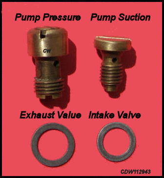
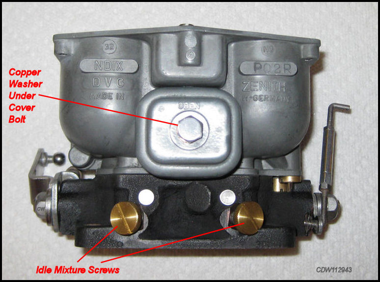
The one copper washer goes under the Jet Cover Bolt. The three different sized aluminum washers go under the Pump Pressure Valve, the Pump Suction Valve and the Float Valve. They are all different sizes. Just be sure the right washer gets under the right valve and that it fits properly. One concern is that some of the aluminum washers may come from the kit with nicks or dings in their flat areas. Look for these as they can cause leaks. Replace the dinged washers.
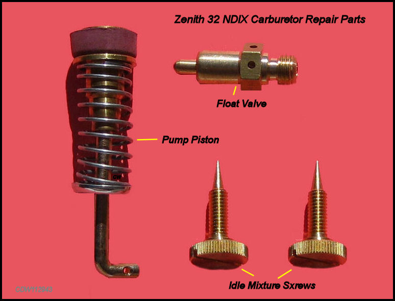 |
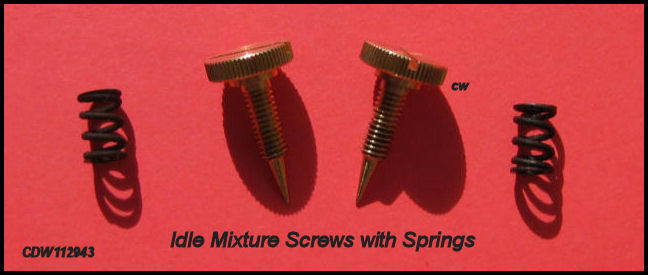
The other metal parts in the rebuild kit consist of the
Pump Piston, Float Valve
and Idle Mixture
Screws. The Pump Piston has a
small hole in the right angle end and is held in place with a
small cotter pin. The
Idle Mixture Screws require a small spring
which does not come with the kit. When removing the
Idle Mixture Screws during disassembly,
don't lose these little
springs.
 |
Disassembly of the
Zenith
32 NDIX
Carburetor.
Separating the Carburetor Top, Main Carburetor Body and Throttle Body.
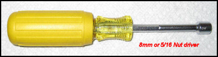
On the top of the carburetor, remove the five (5) six-sided slotted-head bolts as indicated by the arrows below. Save the split washers. Best to use an 8mm or 5/16 nut driver, instead of a slotted screwdriver, to remove these Slotted-head Bolts.
 |
Looking down at the top of the dirty Zenith 32 NDIX Carburetor (before cleaning). |
|
Use an 8mm or 5/15 nut driver instead of a slotted screwdriver! |
Remove the carburetor top from the carburetor
body. The top may be stuck to the body, so a slight
tap with a rubber hammer will free it up.
Don't try to pry it off with a
screwdriver. There is a very thin gasket between
the Carburetor Top and the
Carburetor Body. On one side of the carburetor
top, attached to the carburetor top and sticking down into the body of the
carburetor is the Accelerator Pump Piston.
Gently pull the carburetor top up and away
from the carburetor body so that the
Accelerator Pump
Piston comes out
freely.
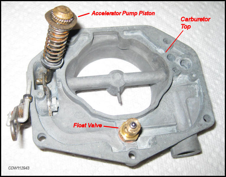
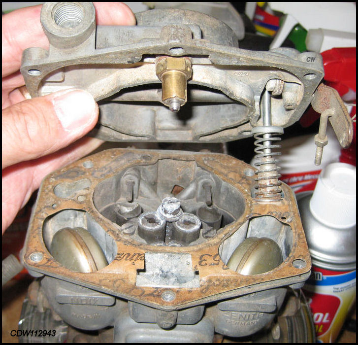 |
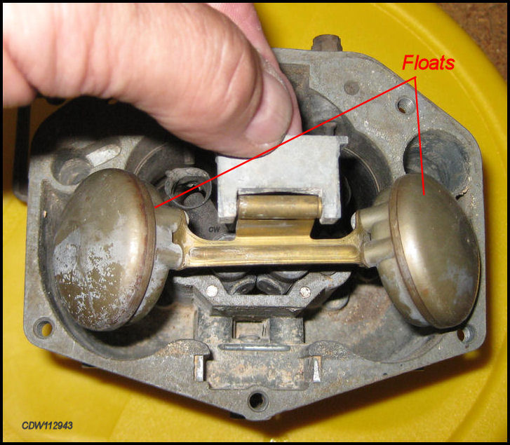
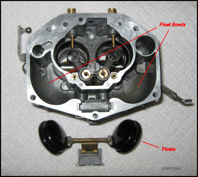
Removing the top of the carburetor exposes the Accelerator Pump and Floats (before cleaning). |
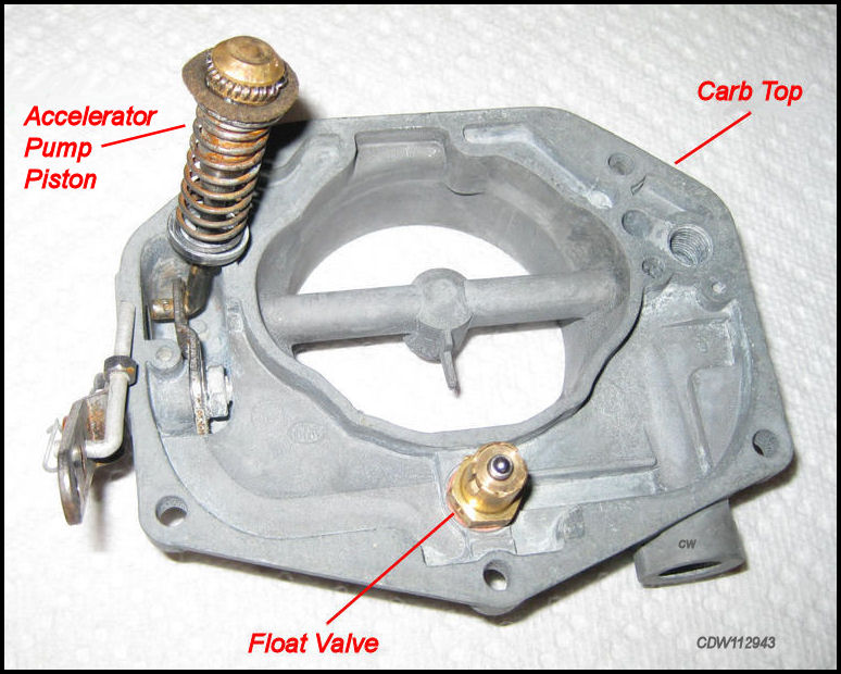 |
Carburetor
Top showing
Accelerator Pump
Piston and
Float Valve,
both of |
Removing the
Floats.
|
The Floats are not attached to the Carb Body and can easily be lifted out. |
|
Main Carburetor Body with Floats (before cleaning). |
|
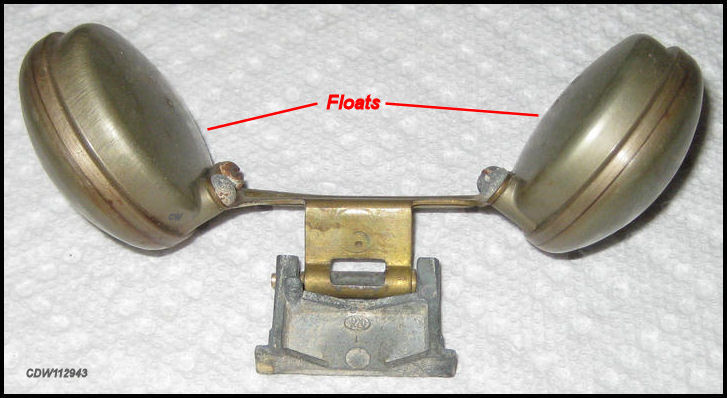
You will
see
Floats that are metal as
shown above, and some that are black plastic. When you |
Removing the Idle Mixture Screws.
 |
Remove
the Idle Mixture Screws
by unscrewing them
counter clockwise,
and |
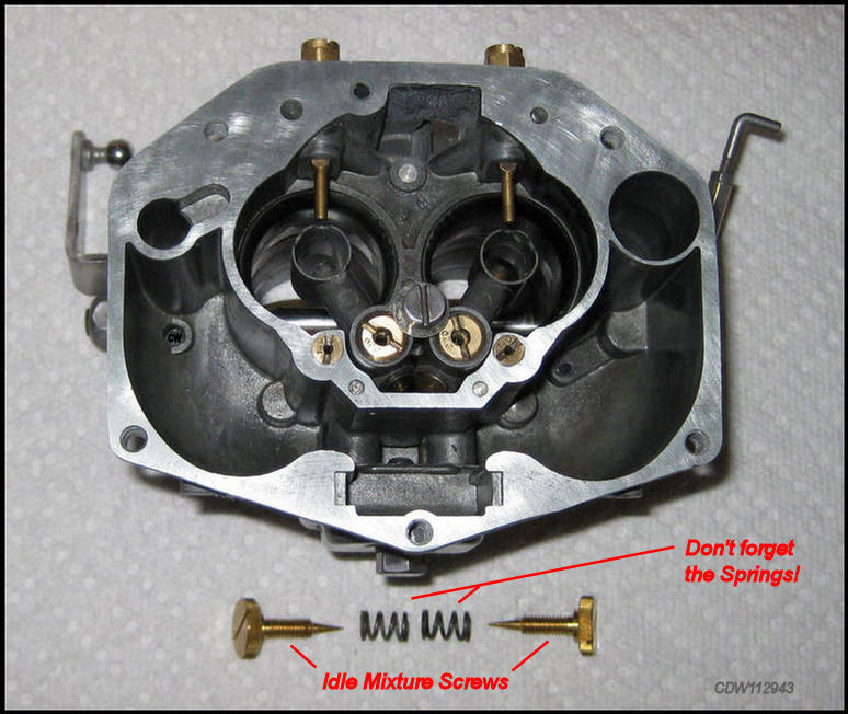
Removing the Idle Mixture Screws is
one of the easier tasks in the rebuilding of a Zenith carburetor. Take them
out by unscrewing them counter clockwise. When
removing the Idle Mixture Screws,
be careful NOT to loose the little springs.
You will get new Idle Mixture Screws
in the rebuild kit, but you won't get a new set of springs. These little
springs have a habit of disappearing, so
keep track of them. There's nothing worse
than ending a carb rebuild with a spring
gone missing!
 |
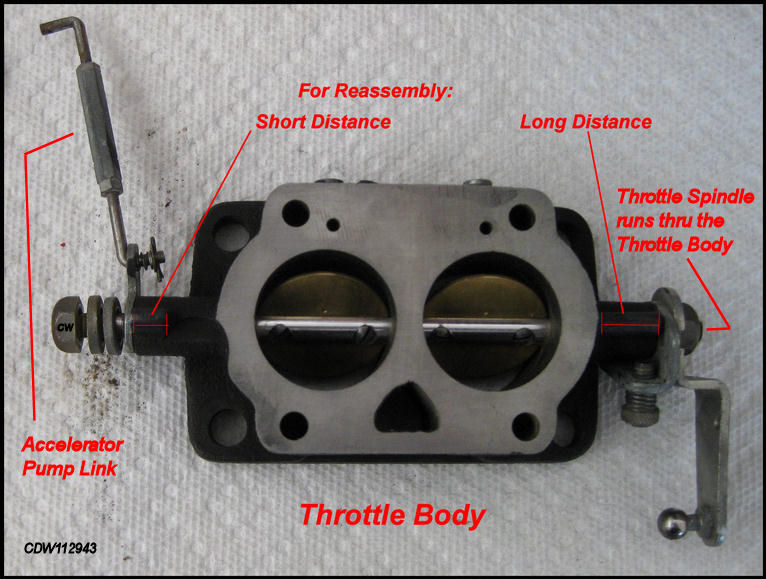
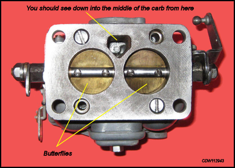
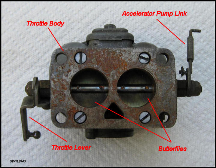
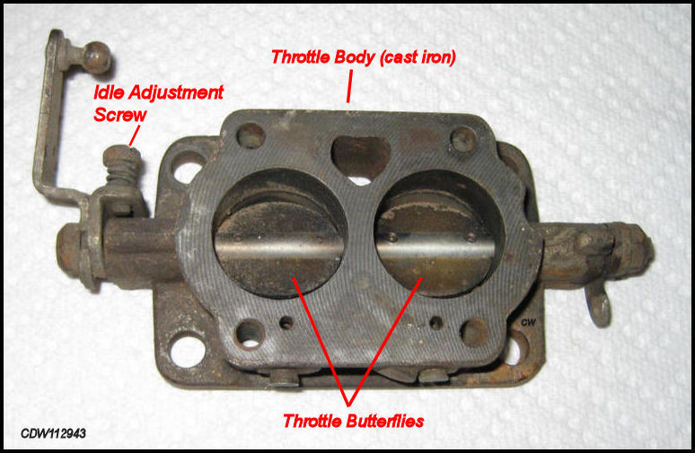
Separating the Throttle Body from the Carburetor Body.
Remove the bottom portion of the carburetor known as the Throttle Body, which contains the Throttle Spindle and the Throttle Butterflies. The Throttle Body is made of cast iron so you may find some rust. Flip the carburetor "bottoms up"! You will see 4 slotted-head bolts. Remove the four Slotted-head Bolts and the bottom part of the carb known as the Throttle Body will come off. If the bolts are stuck, don't try to force them. A little Kroil or Liquid Wrench on them for a few hours will help loosen them up. There is another gasket between the Carb Body and the Throttle Body and sometimes these two parts "stick" together. A light tap with a rubber hammer should separate them. Don't try to pry them apart with a screwdriver!
 |
Looking at the bottom of the Throttle Body (before cleaning). A little rust there. |
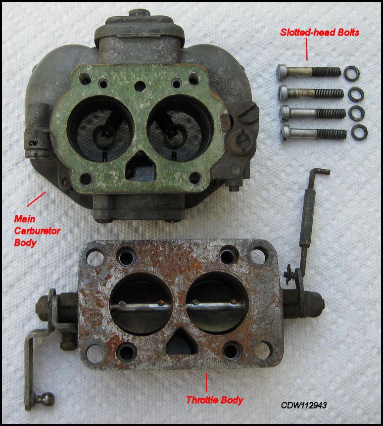 |
Main Carburetor Body and Throttle Body separated (before cleaning). |
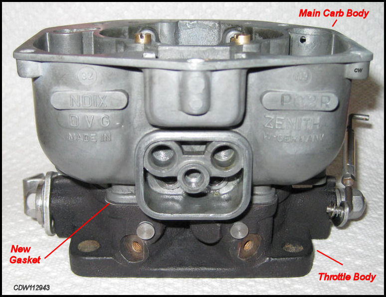
Above you will see the Main Carburetor
Body above and Throttle Body
below after separation but before cleaning.
Notice the green gasket, and the four sloted-head bolts which held
the Throttle Body to the
Main Carburetor Body.
Keep the split washers, unless you
can find new ones the exact same size. Up
until this point, the carb has not been cleaned!
Basic Cleaning.
A rebuild presupposes the carburetor has been used. Hence a basic cleaning is in order before rebuilding. So far you have disassembled your carburetor into its three main parts, including the Carburetor Top, the Main Carburetor Body, and the Throttle Body. And, you have removed the Floats and Idle Mixture Screws. Now it's time to do some basic cleaning of these major parts. This is a very important part of your rebuild. Carburetor cleaner comes in spray cans and also in large "paint-size" gallon cans, most of which include a metal or plastic basket inside the can. Put small parts in the basket to dip into the cleaning solution in the can. This is really handy! You can almost get all three major parts of the carburetor in the "paint can" for cleaning at the same time. Leaving the parts in the solution for 24 hours results in an excellent cleaning of the parts. The parts can then be further cleaned with brushes and then washed with clean water. Extra dirty parts may require additional soaking in the carburetor cleaning solution. The cleaner solution is pretty nasty stuff, so take care to cover your eyes, and keep it off your skin as much as possible.
The cleaning product used in this presentation is shown below. It is a gallon-sized can which includes a plastic basket for small parts that can be submerged into the cleaner solution in the can. It cleaned the really dirty carburetor parts very well and is recommended. It can also be used over and over again, and on other dirty greasy parts. There are other brands of carb cleaner.
In the course of your rebuild: Be Sure to CLEAN ALL the PARTS!
 |
Below are pictures of the three main carburetor parts after preliminary
soaking and cleaning. An old tooth brush works wonders
after the carb parts have been in the cleaning solution.
Another tip that worked really well for the brass parts
was to soak them for a few hours in
alloy wheel
cleaner. Pour a little out of the spray
bottle into a jar and throw in the jets and other brass parts. The alloy
wheel cleaner removes the black stuff that doesn't come off in the carburetor
cleaner solution. Buffing them to bright
metal afterwards definitely
enhances their
appearance.
 |
Carburetor Top: Accelerator Pump Piston and Float Valve will be replaced. |
 |
Main
Carburetor Body: with
Jet Cover
Plate in
place. Nice &
Clean!
"OBEN"
should be on top of the |
 |
Throttle Body: Cleaned with some remaining rust. This part is cast iron unlike the rest of the carb. |
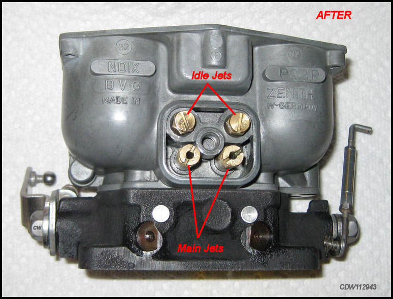
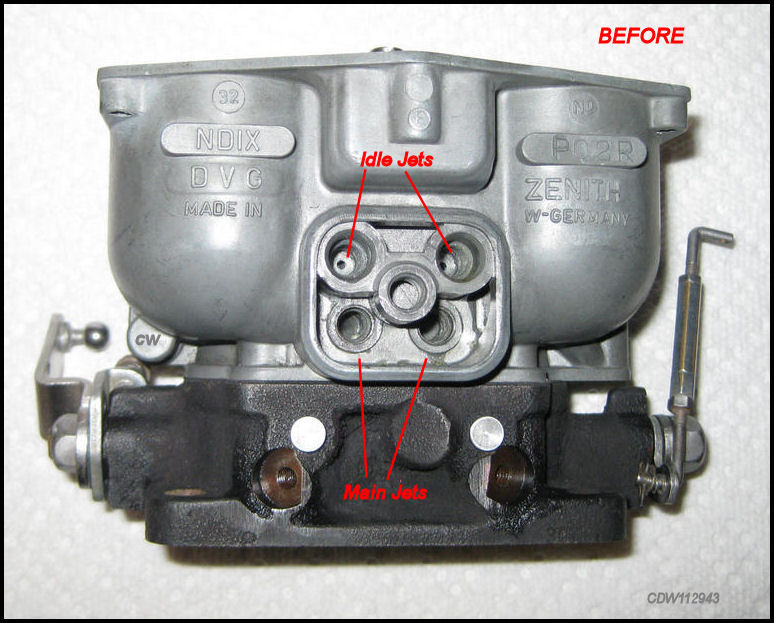
Removing the Main Jets and Idle Jets from the Main Carburetor Body.
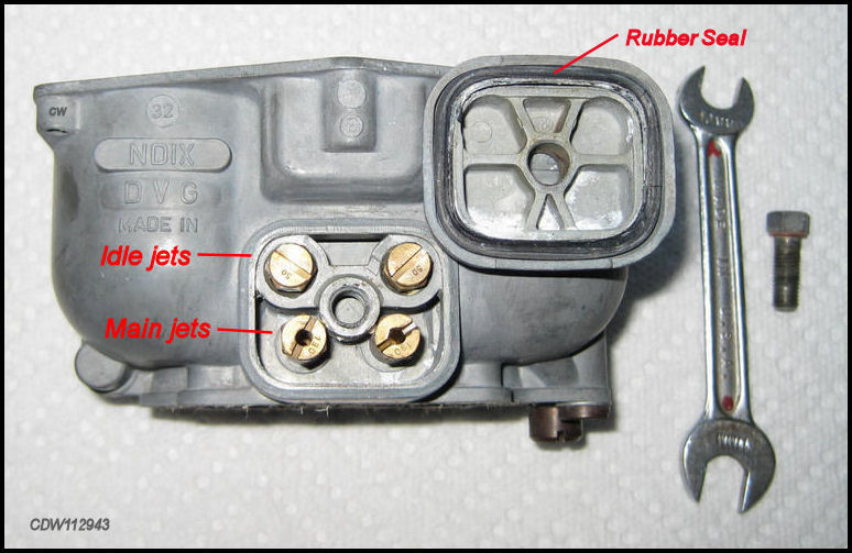
The Main Jets and Idle Jets are located under the squarish cover on the front of the Carburetor Body. Use a 10mm open end wrench or a 10mm socket to remove the bolt. Use an 8mm nut driver (5/16 will also work) to remove the Main Jets and Idle Jets.
 |
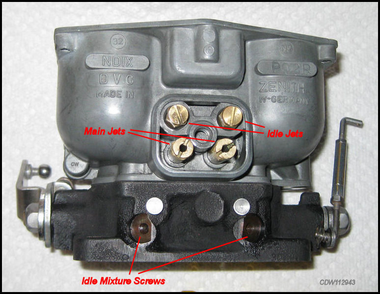
Remove the bolt to reveal the Main Jets and Idle Jets. |
|
Use a 10mm open end wrench or a 10mm socket to remove the bolt. Notice the rubber seal! |
|
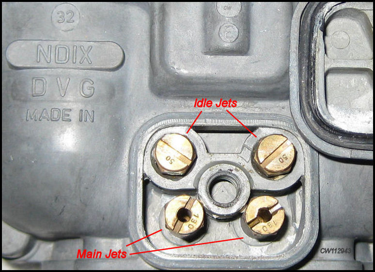
Idle Jets = 50, Main Jets = 130. You know it is for a 1600-Super! |
See table above for Zenith 32 NDIX jet specifications
356-A thru 356-C.
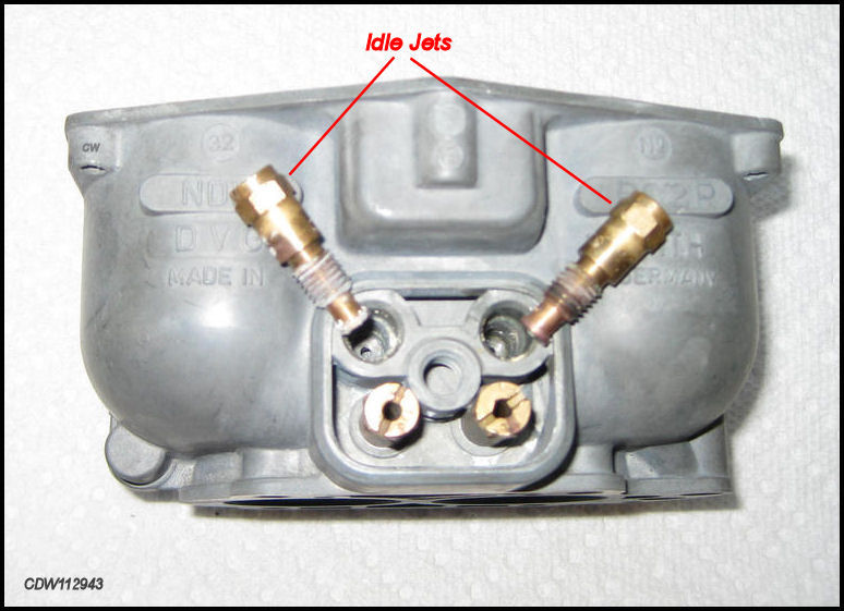 |
Idle Jets are on Top! They need to be cleaned! |
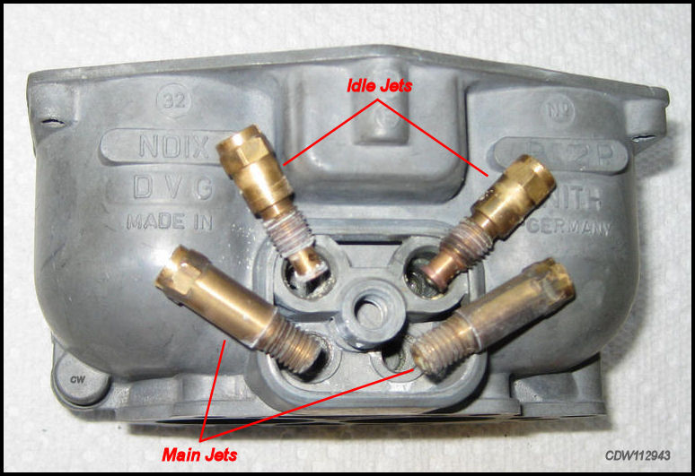 |
Main Jets are on the bottom! They also need to be cleaned! |
Notice different shapes of Idle Jets and Main Jets. Use an 8mm or 5/16 nut driver to remove and replace! |
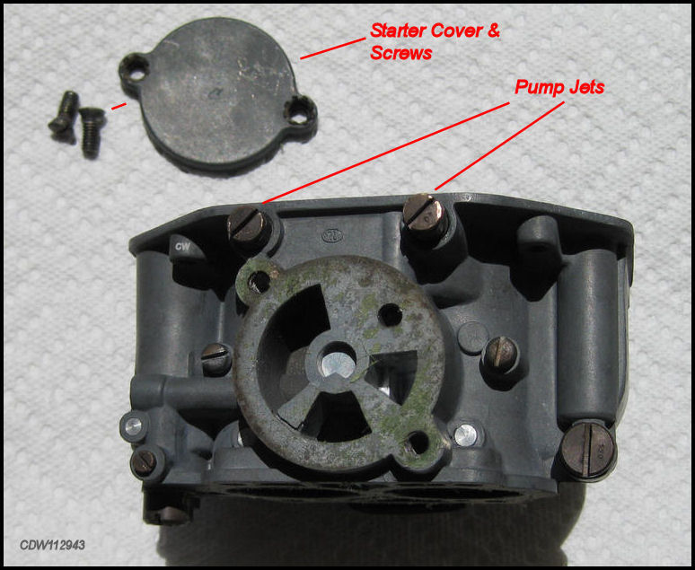
Removing the Pump Jets and Starter Cover.
|
Behind
the Pump Jets
and in the same holes
are
the Accelerator Pump Injection
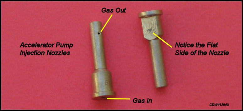
Nozzles. Removal of |
|
There is another gasket between the Starter Cover and the Carb Body. |
|
|
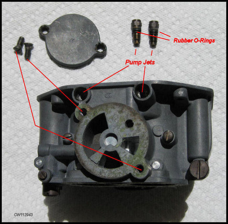
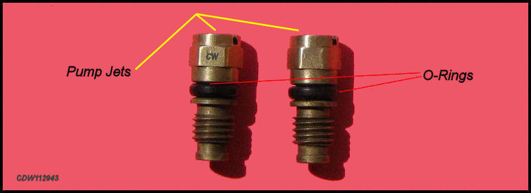
The Pump Jets are best removed using
an
8mm or 5/16 nut driver and the
Starter Cover Screws are removed with a
flat blade screwdriver. The Pump Jets are
brass so if they resist coming out, spray them with a little
Kroil and allow them to loosen up.
New Pump Jet
O-rings should come with the rebuild kit.
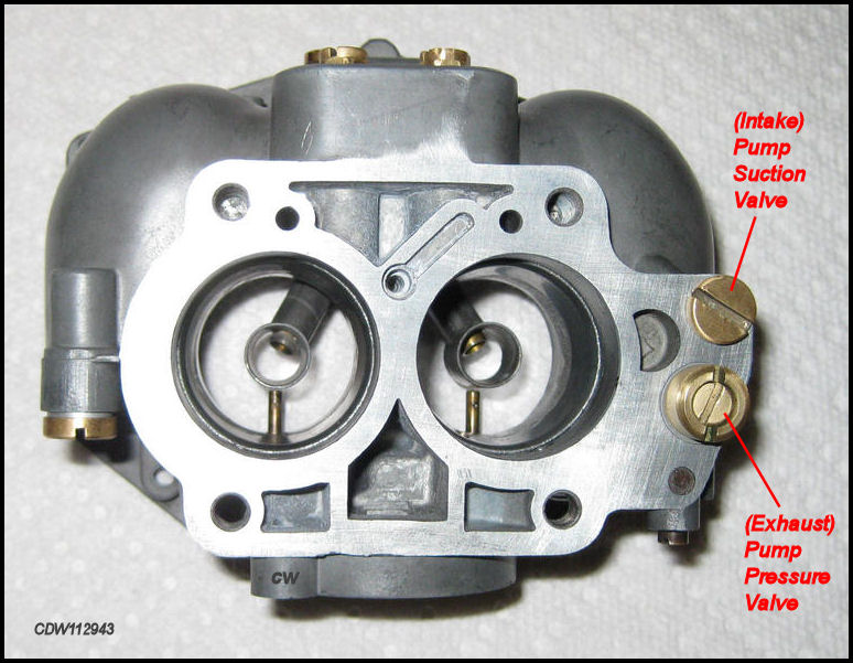
Removing Pump Suction (Intake) Valve and the Pump Pressure (Exhaust) Valve.
 |
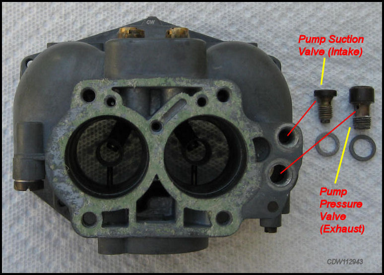
The
Pump Suction
Valve, commonly called the
Intake Valve,
and
the
Pump Pressure Valve,
|
 |
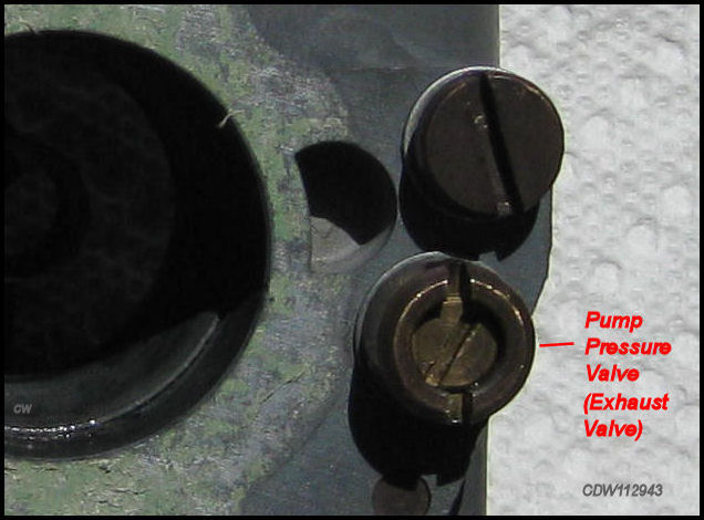 |
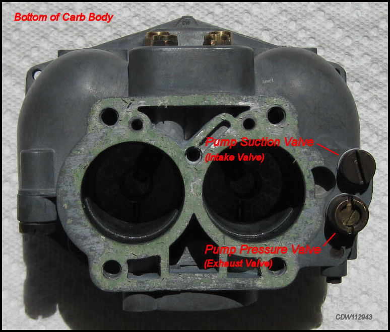
Some CAUTION is advised when removing the Pump Pressure (Exhaust) Valve. |
The
Pump Suction Valve (Intake
Valve)
and the Pump Pressure (Exhaust)
Valve are located on the bottom of the
Carburetor Body
and cannot be removed
until the Throttle Body and Carburetor Body are separated. At
first glance the Pump Pressure (Exhaust)
Valve looks like it's supposed to be removed using a common flat
blade screwdriver. However, the distance between the slits in the top of
the Pump Pressure (Exhaust) Valve are wider
than the average screwdriver. Most carburetor experts suggest
that you not disassemble the
Pump Pressure (Exhaust) Valve, as most don't
need adjustment or rebuilding. Hence,
in order to remove this item without damaging
it, either use a very wide blade screwdriver or a Dzus tool ground flat on
the end.
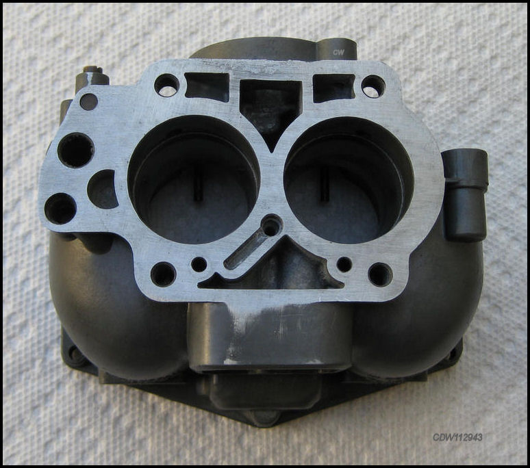
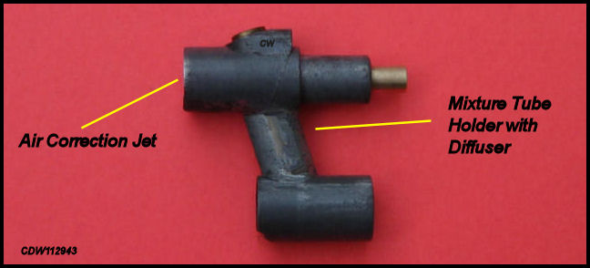
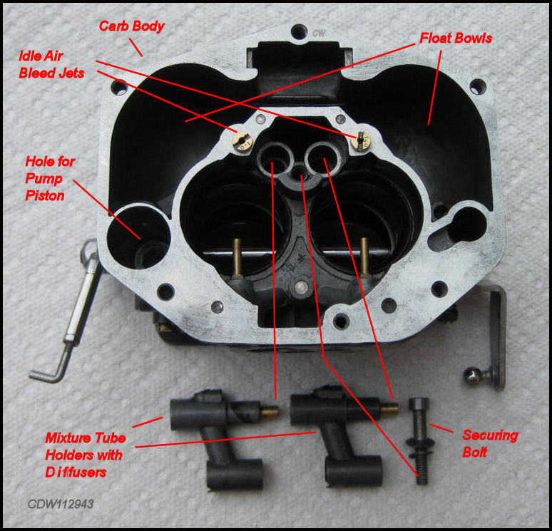
Removing the Mixture Tube Holders (with Diffusers).
|
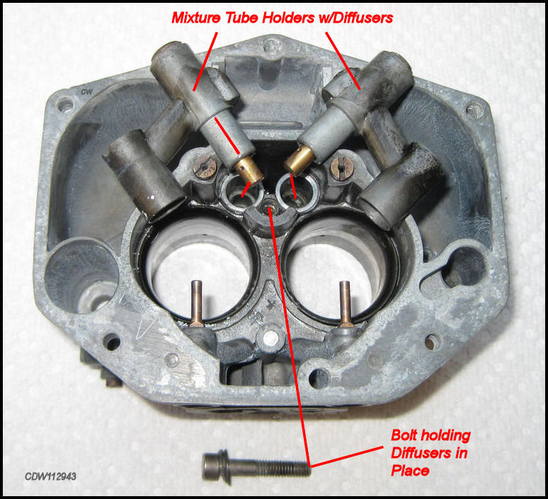
Now remove the Mixture Tube Holders with Diffusers! |
|
Having removed the small bolt in the center, the Mixture Tube Holders w/Diffusers are lifted out! |
|
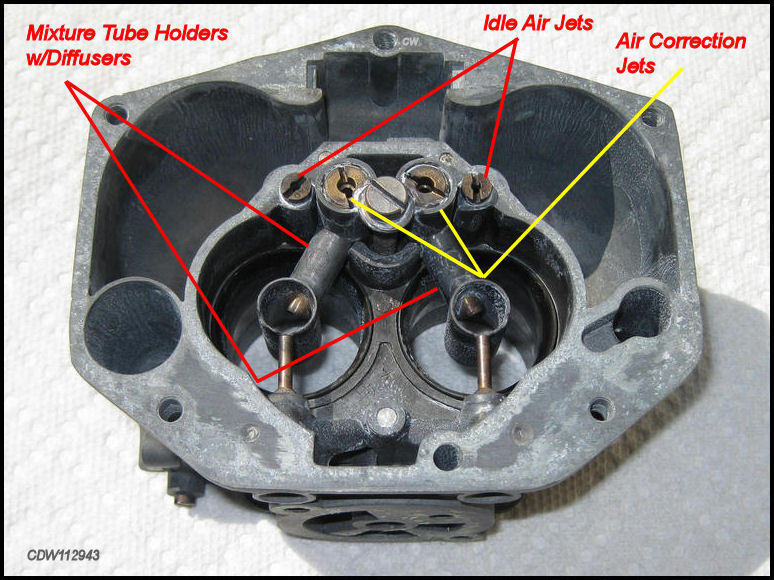
Removing these Mixture Tube Holders
can be difficult! First, the small bolt shown in
the picture above, which holds the two Mixture Tube
Holders in place, is removed. Next, the
Mixture Tube Holders are lifted out. The
area marked with the red line in the picture above slides down into the hole
in the central carb body. Normally, this should simply
be a lift out. But often fuel residue gets between the
Mixture Tube Holders and the walls of the
holes and makes them stick in place. Some say, tap the side of the
Mixture Tube Holders
lightly to break them loose. Too hard a tap and you can break one
(guess how I know!). A little
Kroil around the edges, together with ten
minutes and a light tap, and you should be able to lift them out. Another
way to remove the Mixture Tube Holders is
to use a puller connected to the threads where the Air
Correction Jets sit. A little patience
helps here!
Disassembling & Cleaning the Mixture Tube Holders (with Diffusers).
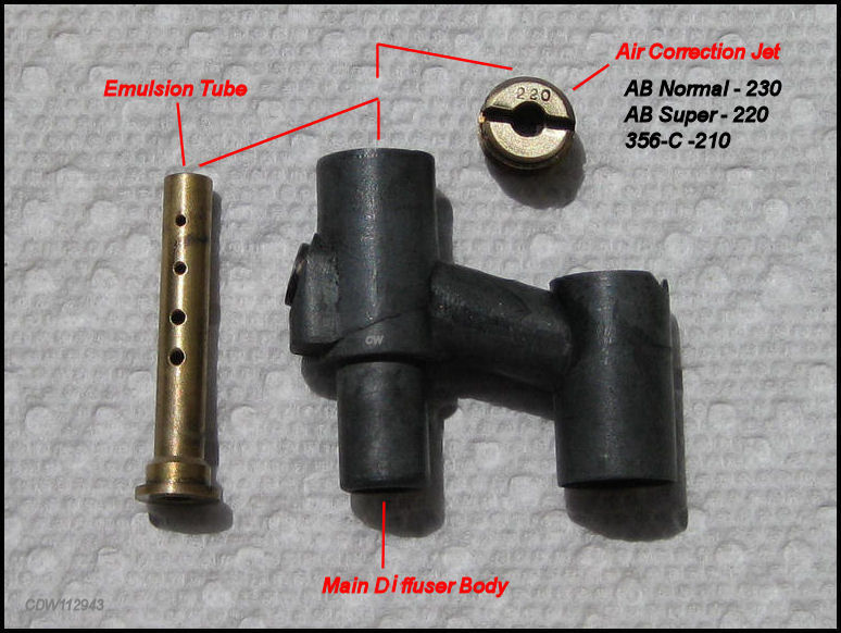 |
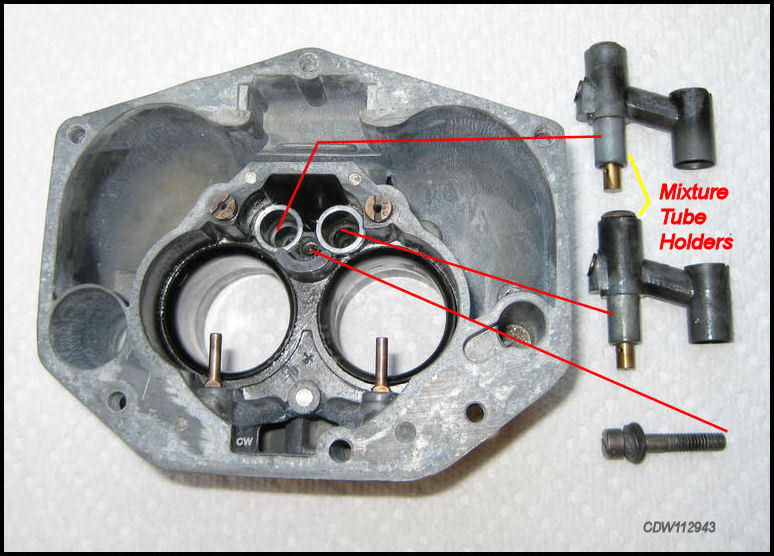
Once the Mixture Tube Holders (with Diffusers)
are removed from the main carb body, they should be disassembled and
cleaned. A soak in carburetor cleaner prior to disassembly should do it.
Take a flat blade screwdriver and remove the Air Correction
Jet. If it resists unscrewing, use a
little Kroil and let it soak. This should
make removing it easy. Disassemble the three parts as shown above. Check
for plugged holes in the Emulsion Tubes
and the Air Correction
Jets. A strand
of fine wire or thick nylon fishing line can be used to clean out the holes
of any fuel residue or miscellaneous crud. Then reassemble the
Diffusers. Before tightening the
Air Correction Jets in place, the flat surface
of the jet was buffed to bare metal so that the jet's size markings were
clearly visible and for appearance purposes.
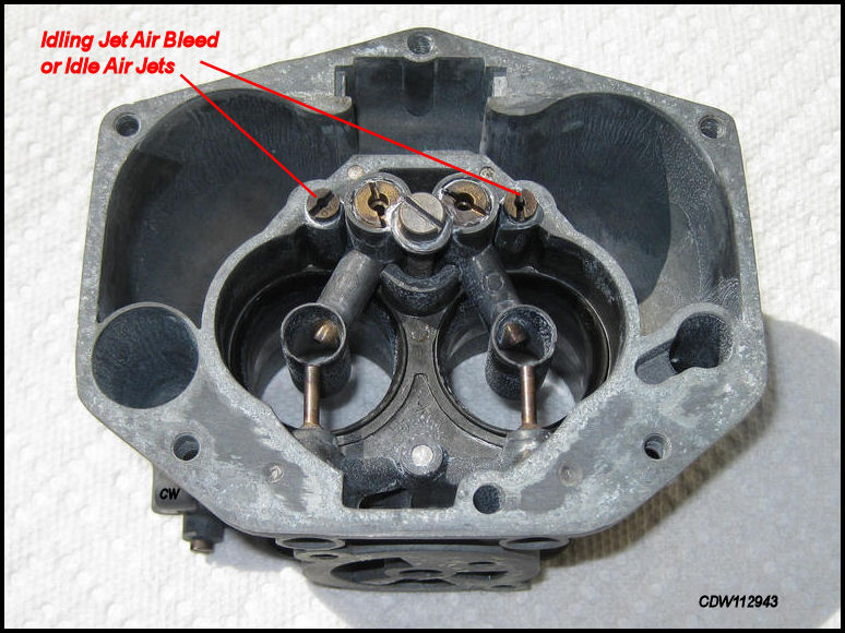
Removing & Cleaning the Idling Jet Air Bleed or Idle Air Jets.
 |
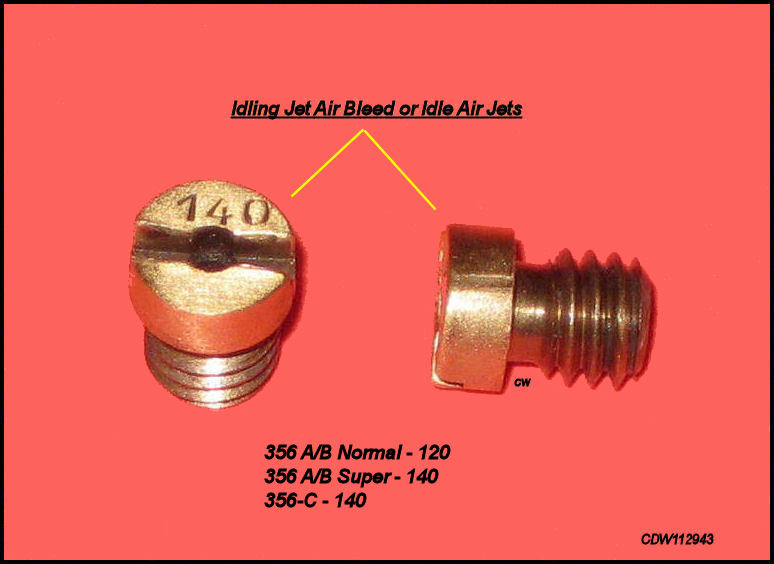 |
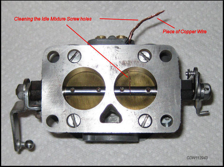
Removing and cleaning the Idle Air
Jets or the Idling Jet Air
Bleed, per the parts book, is very simple. Use an
appropriate flat blade screwdriver. Keep
track of these little guys as they are easily lost! One
caution, removing them while the carb is still on the engine is problematic.
Drop one down the hole, and you have a problem! Soaking them in
some carburetor cleaner will eliminate any accumulated crud, and a piece
of copper wire or nylon fishing line put through the hole will insure no
obstructions. See the table for what size Idle Air
Jet to use, 120 or 140.
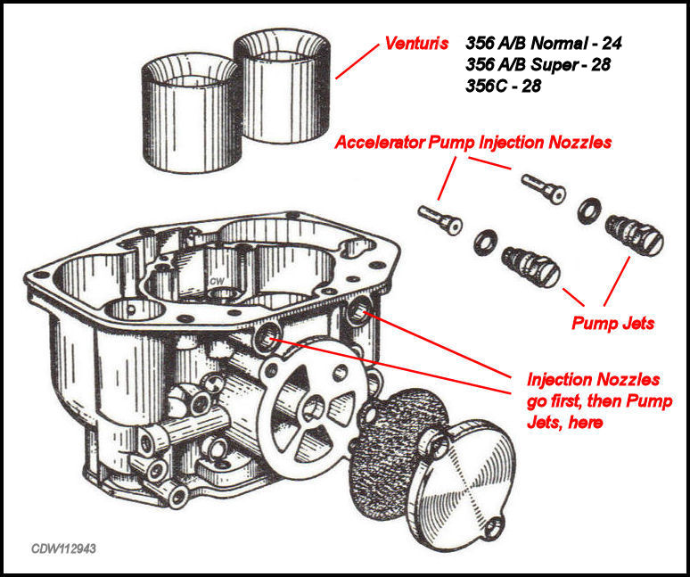
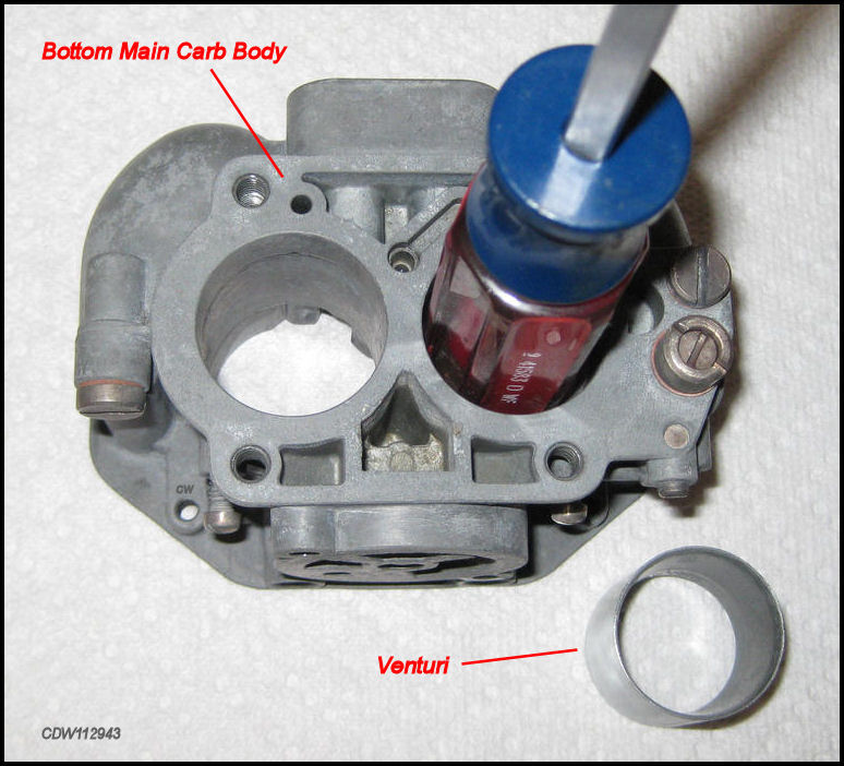
Removing the Accelerator Pump Injection Nozzles and the Venturis.
|
|
The
line drawing above makes it clear where
the Injection
Nozzles and the
Pump Jets
go.
Basically, |
|
|
|
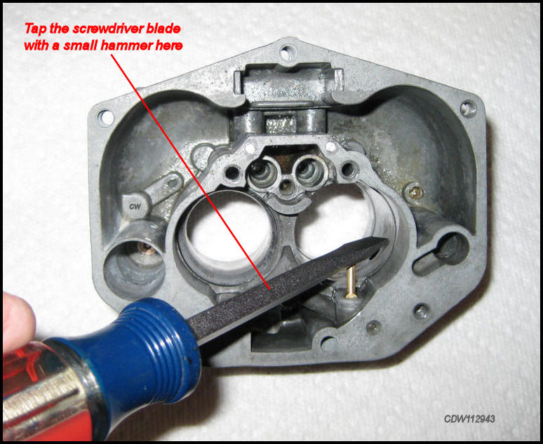
To remove
the Injection Nozzles,
first remove the
Pump Jets,
then position the carb on it's side. Place |
|
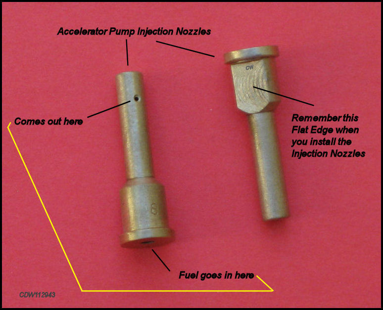
Cleaning
Accelerator Pump Injection Nozzles
can be first accomplished
by soaking them in
carburetor |
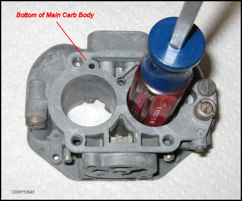
Removing
the
Venturis comes next. But before you start,
it is good to know that stock
Venturis come |
|
Unconventional, but effective way of removing a Venturi. Just tap the other end of the screwdriver. |
|
Most have a special tool to remove the Venturis. See the explanation below for this Venturi removal. |
Removing the Accelerator Pump Injection
Nozzles was harder than anticipated.
First the Pump
Jets were removed as shown previously. The
Injection Nozzles are brass and extend into
the inner part of the carburetor as shown in the image above. They go into
the same holes as the Pump Jets, which were
easy to remove. In this case, the Injection
Nozzles were stuck in place. A little
Kroil was put into the holes, and left a
few minutes to work. The Carb Body was set
on it's side, and the flat blade of a screwdriver was placed on the end of
the Injection Nozzles and tapped lightly.
They came right out.
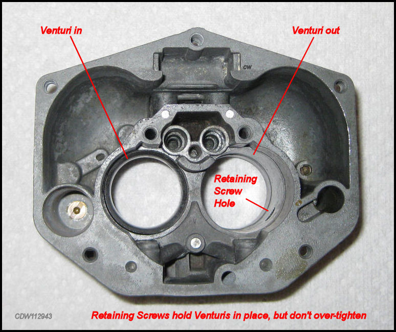
Removing the Venturis was the most difficult task to do without specialized tools. There are two Venturis in each Zenith 32 NDIX Carburetor, and more often than not they stick in place and refuse to come out. Before removing the Venturis, the two Retaining Screws have to be backed out and both Mixture Tube Holders (with Deffusers) must be removed. In addition, the Pump Jets and the Accelerator Pump Injection Nozzles must be removed. To deal with stuck Venturis, some gently tap the Venturi out using a round disk the same diameter as the Venturi attached to a rod. One recommendation was to use a 31mm exhaust valve to tap out the venturi. In any case, without this special tool or a right sized exhaust valve, a screwdriver with a plastic handle about the diameter of the Venturi was placed on the bottom side of the Venturi and lightly tapped. It came right out! Or try a Porsche 31mm exhaust valve!
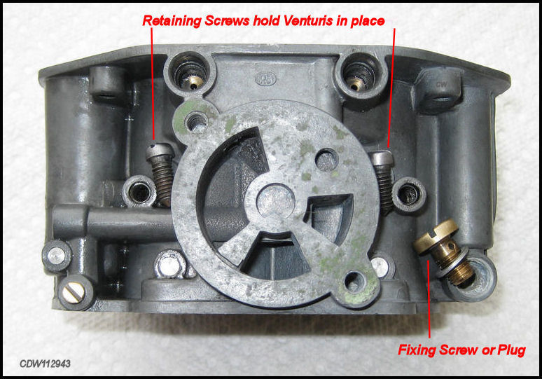
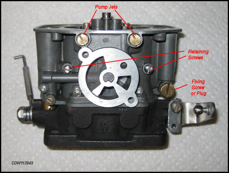
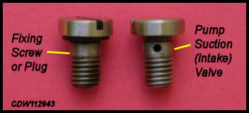
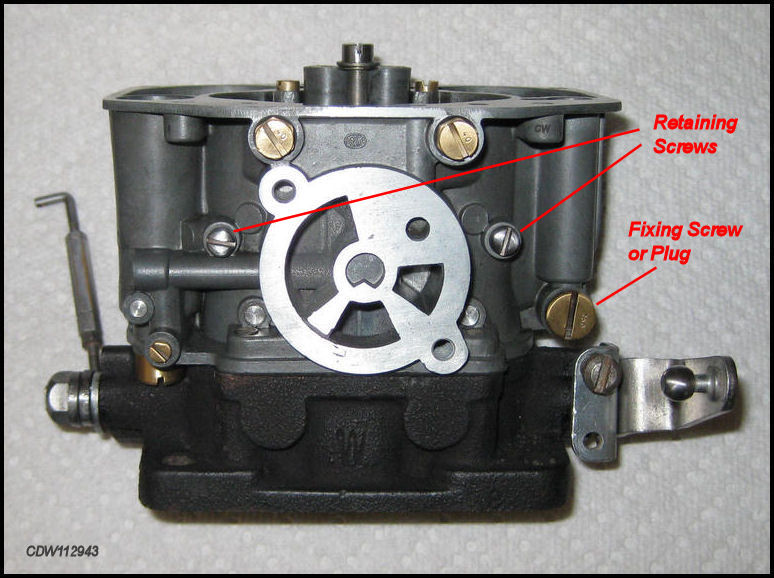
Removing & Cleaning the Retaining Screws & the Fixing Screw or Plug!
|
|
The two Retaining Screws hold the
Venturis in place and
do not have to be backed out all the way
to remove the Venturis. "Fixing Screw"
is a term used in the parts book. It
really should be called a Plug, as
it allows the Zenith float level gauge to
be used to check the float levels. All three were removed, cleaned and buffed
to bright metal.
Refacing the flat areas on the Throttle Body, Main Carb Body and Carb Top.
 |
Top Surface of Throttle Body. Notice the Throttle Body has been blackened with HT flat black paint. |
 |
Above is the Bottom Surface of Throttle Body. |
 |
Top Surface of Main Carb Body. |
 |
Above is the Side Surface under the Starter Cover on the Main Carb Body. |
 |
Above is the Bottom Surface of Main Carb Body. |
 |
Above is the Bottom surface of Carb Top. |
As you can see in the earlier pictures, the flat surfaces on the
Main Carb Body and the
Throttle Body still had some accumulated
crud and gasket material after the soak in the carburetor cleaner.
Putting a sheet of 400 grit
sandpaper on a flat concrete floor and rubbing
the flat edges against the sandpaper cleaned
them up for a better fit when the carburetor
is reassembled, and helps to prevent future
leaks.
The cast iron Throttle Body was cleaned and "blackened" with a small brush using high temperature flat black paint to match the original appearance of the carburetor.
In some cases, where a thicker then stock gasket was used between the Carb Body and the Carb Top, the surfaces of either may be warped due to over-tightening of the Slotted-Head Bolts. This warping can cause leaks. If you find this to be the case, you may need to have an expert do a professional repair rather than trying to do it yourself. You don't want leaks in your newly rebuilt carburetor, particularly after you have reinstalled it back in the car.
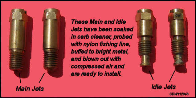
Checking and Cleaning of the Main Jets and Idle Jets.
 |
 |
All the jets and valves are made of
brass. After removing
them from the Main Carb Body, they were
soaked in carburetor cleaner to remove any fuel residue. And as you can see
in the earlier pictures, there was a fair amount of crud on them.
They were then soaked for
a couple of hours in alloy wheel
cleaner, the kind you can buy in spray bottles
at your local auto parts store. This removed
the black on the brass that did not come off with the carburetor
cleaner.
Next, the top of each jet and valve was buffed on a buffing wheel to bright metal. Lastly, the holes in the various jets were cleaned using small wires and some fairly thick nylon fishing line to ensure no accumulated residue was left, and they were blown out with an air pressure nozzle. As you see them above, they are clean and ready to be reinstalled in the carburetor.
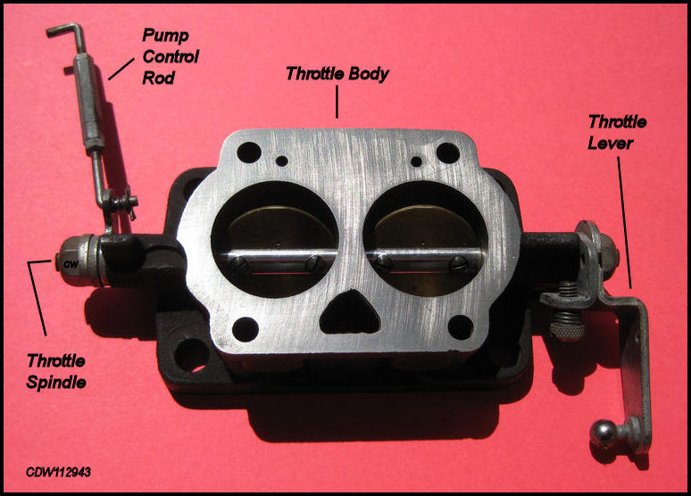
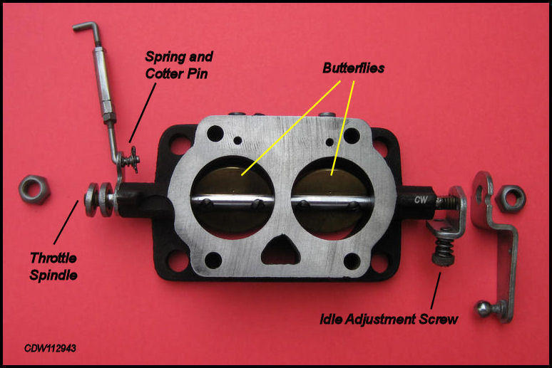
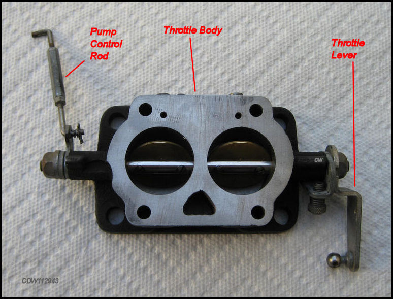
Cleaning the Throttle Lever, Pump Control Rod and Tension Spring.
|
Above, Throttle Lever and Pump Control Rod and related parts before final cleaning! |
|
Disassembly started using 12mm open end wrench at each end of Throttle Spindle. |
|
Exploded-View of the Throttle Spindle, Throttle Lever and Pump Control Rod, and related hardware. |
|
All Throttle Spindle parts were cleaned, buffed to bright metal, and reassembled. |
|
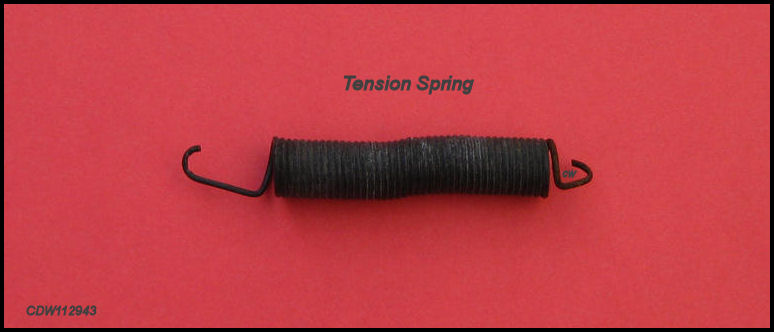
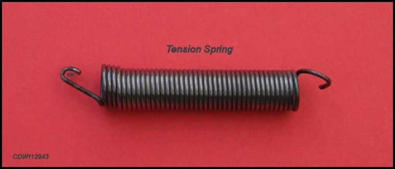
A little buffing of the Tension Spring makes it look like new. |
|
Many carb rebuilders advise replacing this spring with a new one during a rebuild. |
In most cases, it isn't a very good idea
to remove the Butterflies, unless
there is something obviously wrong with them or for some reason they are
loose, bent or excessively dirty. The
Butterflies should open and close freely
on the Throttle Spindle. The
Tension Spring was buffed on the buffing
wheel to bright metal. Some carb experts suggest that the
Tension Spring should be replaced in any
rebuild. Some rebuilders re-plate
the Throttle Lever, Pump Control
Rod, Tension Spring and related
hardware with clear cadmium plating or
zinc plating that leaves
these parts looking
unnaturally silver, so for this rebuild,
they were just cleaned and buffed to bright metal.
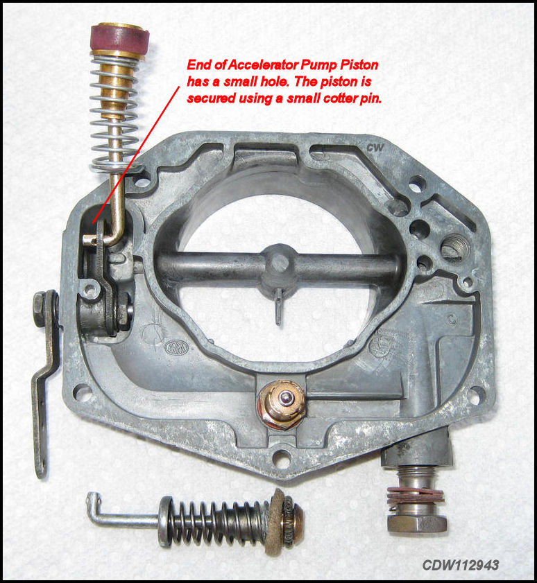
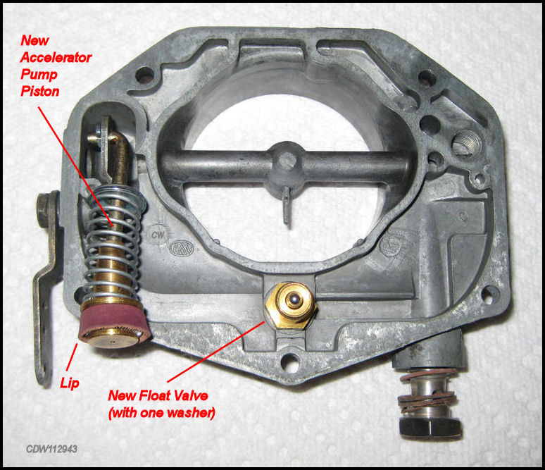
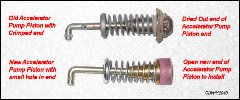
Replacing the Accelerator Pump Piston and Float Valve.
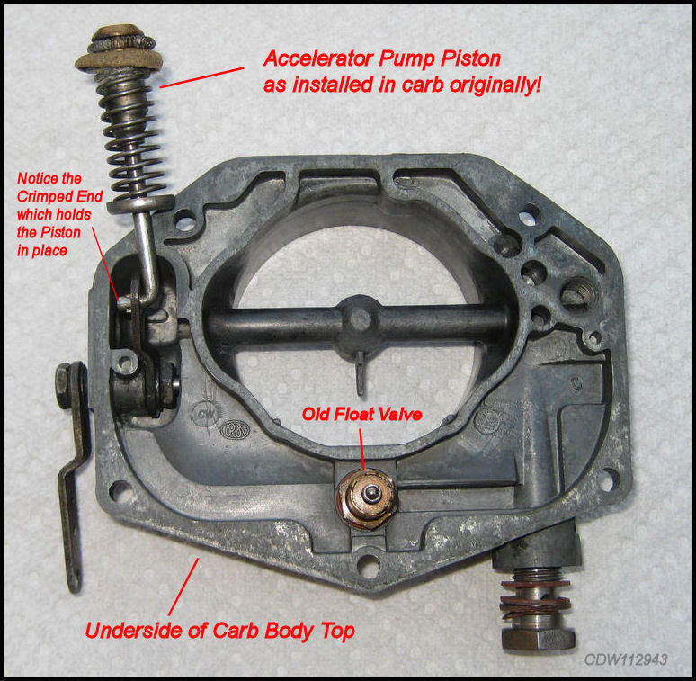 |
If the end
of the old Pump
Piston has crimps to hold it
in place, rotate the large lever so the small lever |
 |
 |
 |
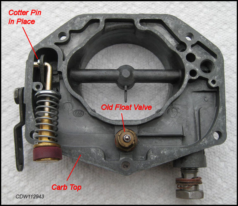
Old Float Valve is removed with 12mm open end wrench or 12mm deep socket. Don't forget washer! |
|
A small cotter pin will be used to secure the new Accelerator Pump Piston to the small pump lever. |
|
|
Cotter pin in place securing Accelerator Pump Piston. |
|
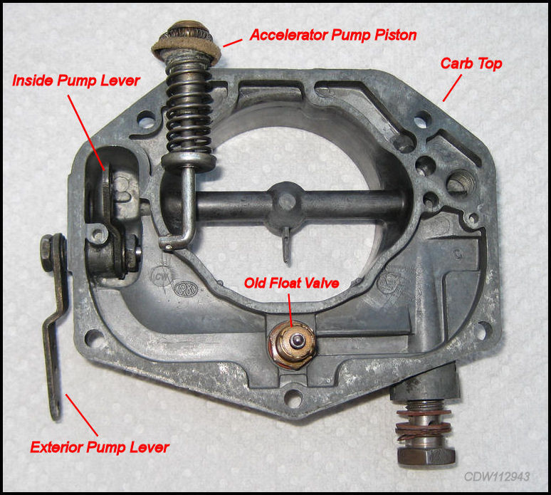
In the first picture above, see the Accelerator
Pump Piston as it was originally installed when the carburetor
was opened up. Notice the end is dried out and deformed
probably eliminating its capacity to pump fuel. Also notice the
metal end with the right angle is still attached to the
Inside Pump Lever. Removing the
Accelerator Pump Piston requires moving
the exterior lever down so that the lever inside the carb top moves up and
allows the Accelerator Pump
Piston to be removed. The second picture shows the
Accelerator Pump Piston removed. The hole
in the Inside Pump Lever allows the crimped
end of the Pump Piston to go through the
lever and the crimped end holds the Pump
Piston in place. When you look at it carefully, you will see how
this works.
If your carburetor has previously been rebuilt, you may see a hole in the end of the Accelerator Pump Piston and a small cotter pin in place. Before replacing the Carb Top, the Accelerator Pump Piston's plunger lip (leather or other?) should get oiled and "massaged preventing a dry out".
Reassembly of the Zenith 32 NDIX Carburetor.
Reassembly is relatively easy. Just remember where everything goes! With all the little and similar looking parts, pictures should be taken at every stage, before and after. That way, there's no reason to screw up the reassembly. So here goes!
Installing the Venturis and Retaining Screws.
|
Each Zenith 32 NDIX
Carburetor has two
Venturis.
In the picture above, the one on the left is in
and |
|
|
After the Venturis have been installed, lightly tighten the Retaining Screws. |
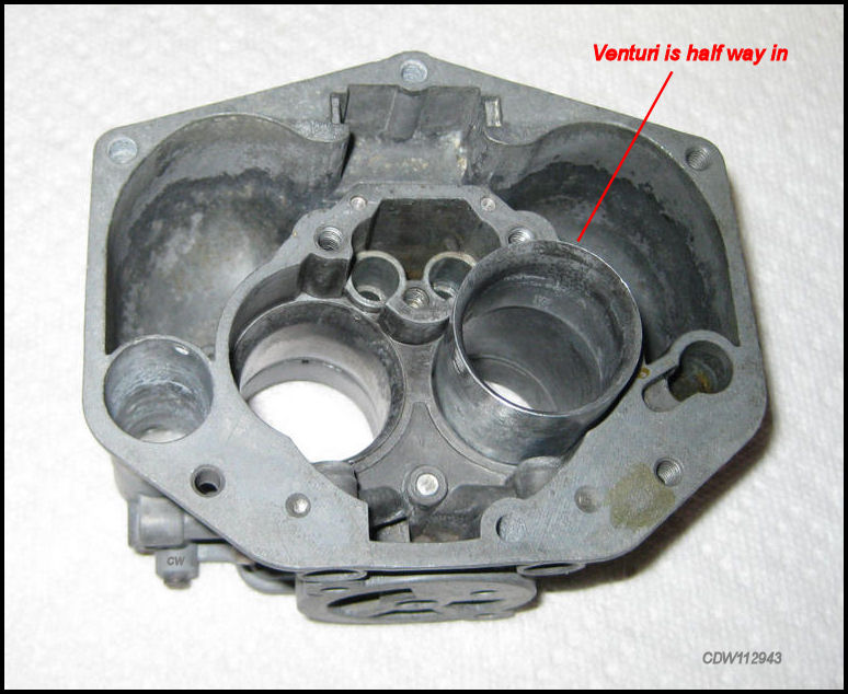
The Venturis, once cleaned, can be
dropped back into the Carb Body from the
top. They should just slide in. If they do
not go all the way in, a light tap with a
small wood block should make them flush. Once installed, tighten the
Retaining Screws. Be
careful not to over tighten the
Retaining
Screws as that may
dent the Venturi
possibly making it difficult to
remove them next time.
Installing the Pump Pressure (Exhaust) Valve and Pump Suction (Intake) Valve.
|
Looking
at the bottom of the
Carb
Body above,
the
Pump Suction (Intake)
Valve
and Pump Pressure |
|
When you are installing the
Pump Suction (Intake)
Valve
and Pump Pressure (Exhaust)
Valve,
add a |
 |
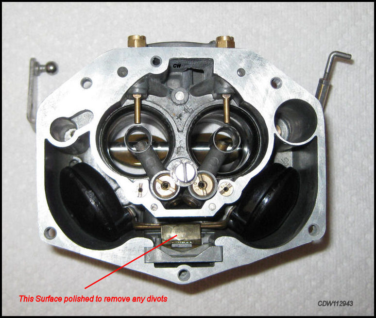
Surface on the bottom of the Main Carb
Body was done
with 400 grit
sandpaper placed on a flat floor. |
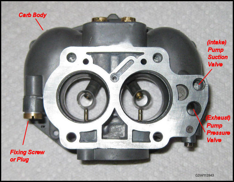
The Pump Suction (Intake) Valve and Pump Pressure (Exhaust) Valve must be installed before the Main Carb Body and the Throttle Body are reassembled together. Otherwise once together, they cannot be accessed easily. Don't mistake the Pump Suction (Intake) Valve for the Fixing Screw. They are very similar! The Pump Suction (Intake) Valve has a small hole on the side, the Plug does not!
Removing and tightening the Pressure (Exhaust) Valve requires a wider than normal flat blade screwdriver in order to avoid messing up the slot on the top of the Pressure (Exhaust) Valve. Just be warned that when working on this item, a normal screwdriver may not work well!
Reassembly of the Main Carb Body and the Throttle Body.
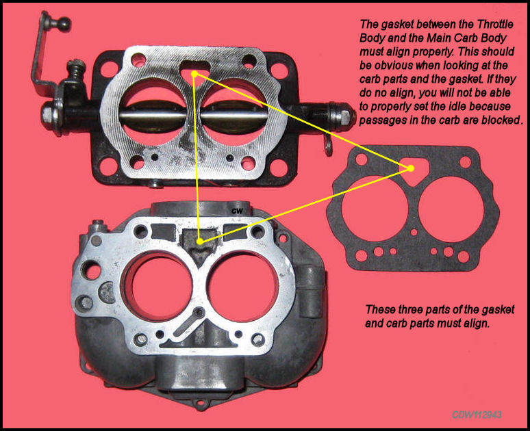
One common mistake made when assembling the Carb Body and the Throttle Body is to misplace the gasket between them. In the images below, notice the triangular holes in the Throttle Body, Carb Body and gasket. These openings have to coincide. If they do not, passageways inside the Carb Body will become blocked and it will become impossible to properly set the carburetor's idle.
|
Above, the
Main Carb Body
is mounted onto
the Throttle
Body with a
new
gasket
in between, held |
|
|
When mounting the Carb Body on the Throttle Body with gasket, make sure everything aligns. |
|
Looking at the bottom of the Throttle Body w/four Cheesehead Bolts in place. Don't forget the washers! |
One common mistake made when assembling
the Carb Body and the
Throttle Body is to
misplace the gasket between them. In the
images above, notice the triangular holes in the
Throttle Body, Carb Body and gasket.
These openings have to coincide. If they do not, the passageways inside the
Carb Body will become blocked and
it will become impossible to properly
set the carburetor's idle.
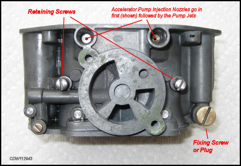
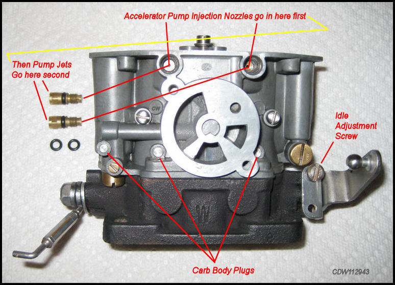
Installing the Pump Jets and Accelerator Pump Injection Nozzles.
|
Notice that
the Injection
Nozzles have
a flat side that must coincide
with the
hole in the carb
body.
The |
|
Inspect the rubber
O-Rings
on the
Pump Jets
before installation. New ones come with a rebuild
kit. |
|
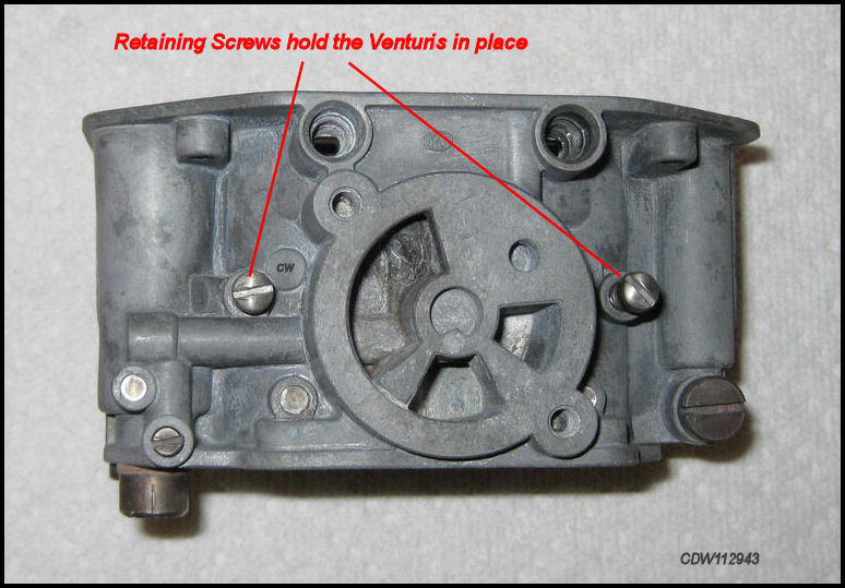
Retaining Screws hold the Venturis in place. Don't over tighten! |
The two Pump Jets go in the same hole
as the Accelerator Pump Injection Nozzles and
are located at the top of the Carb Body above
the Starter Cover.
Notice
that the Injection
Nozzles have
a flat side that must coincide
with the hole in the carb body. The
Pump Jets are best installed with an 8mm or 5/16 nut
driver. The Retaining Screws which
hold the Venturis in place are located in
the middle of the Carb
Body on both sides of the
Starter Cover. The
Fixing Screw is simply
a plug for access to the carburetor when using a
Float Level Gauge,
factory tool
P77,
used to measure
Float Level.
Be careful, the Fixing Screw
looks very much like the
Pump Suction (Intake) Valve
that is fitted to the bottom of the
Main Carb Body.
Mix these two up and you will have a non working carburetor!
Installing the Fixing Screw (Plug).
 |
 |
"Fixing Screw" is a parts book term, a Plug that screws in to seal the hole for the Float Level Gauge. |
Mixture Tube Holders w/Diffusers, Air Correction Jets and Idle Air Bleed Jets.
 |
 |
Make
sure holes in
the
Carb
Body
for the
Mixture Tube
Holders
are clean and free of fuel
residue.
|
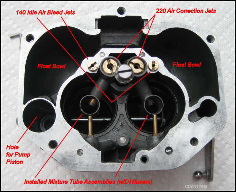 |
220 Air Correction Jets
+
140 Idle Air Bleed
Jets =
356 A/B 1600
Super. The Idle Air Bleed
Jets are
just |
The Air Correction Jets are screwed
into the Mixture Tub Holders first, and
then the Mixture Tube Holders are installed
into the holes in the Carburetor Body. It
is helpful to wipe some hi-temp anti-seize
paste around the base of each Mixture Tube
Holder and in the holes in the Carburetor
Body to prevent sticking problems in the future. The
Idle Air Bleed Jets located next to the
Mixture Tube Holders can be installed separately
and just screw in.
Installing the Main Jets and Idle Jets.
 |
See chart on Page 3 for stock
Main Jet and Idle
Jet sizes for 356
Porsches.
 |
Main Carb Body without Main Jets and Idle Jets installed. |
|
|
Main Jets and Idle Jets are best installed with an 8mm or 5/16 nut driver rather than a screwdriver. |
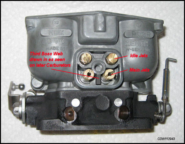
Main Jets and Idle Jets look very much alike, so be sure that you are installing the right jets in the right places! See the images above. Idle Jets go on top and Main Jets go on the bottom. Just be sure they are clean and not clogged up with fuel residue. The Main Jets and Idle Jets are very easy to remove and replace, but are best installed with an 8mm or 5/16 nut driver rather than screwdriver. These jets are made of brass and can be damaged more easily using a screwdriver.
When installing these jets, just note the differences in shape and be aware of where each goes. Idle Jets on top and Main Jets below. The jet sizes are clearly marked on the top of each jet.
Installing the Idle Mixture Screws.
 |
|
Before
installing
Idle Mixture Screws, blow
out the holes with compressed air and
run a thin wire |
|
|
Notice: "OBEN" is on top of the Jets Cover where it's supposed to be. |
Installing the Floats.
 |
Some
Floats are metal and some
are plastic like the above. Before installing
the
Floats, whether they |
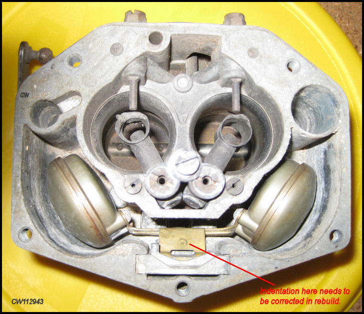
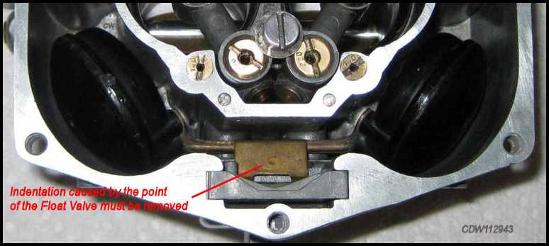
|
This
Indentation caused by the point of the
Float Valve
shown above must be removed or
Float
Level |
 |
When
reassembling your carburetor, remove
the Floats,
and
look at how they
fit
in the Carb
Body! The |
After installing the Floats,
MAKE SURE that the Floats do not contact any portion
of the sidewalls of the Float Bowls. Any interruption in movement
of the floats will adversely affect the float level.
Installing the Jets Cover Plate.
|
The
Jet Cover Plate
Gasket is new and should come with the rebuild
kit! Before installation of the |
|
Idle Mixture Screws are new and should also come with the rebuild kit. |
|
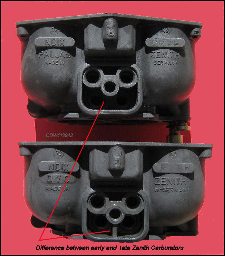
|
The image above illustrates the difference
between the early and
later
Zenith Carb
Bodies as it relates |
The Jets Cover Plate and
Gasket are often the source of
fuel leaks. This can occur if the gasket
is not set correctly or is old or cracked. It can also occur if the
Jets Cover Plate is
warped or bent from too much tightening of the Cover
Bolt. Placing the Jets Cover
Plate on a flat surface may show that it is not sitting flat and
thus not properly sealing the jets cavity. Some say that resurfacing
the cover plate with 400 grit sandpaper on a flat surface can solve the problem.
But if the jet cover is warped, refacing
the jet cover won't solve the problem. The inner
face of the jet cover will bottom out on the boss inside preventing the rubber
gasket from being squeezed and sealing properly. This situation is worse
with the early carbs because the boss has only two support webs vs. the later
boss which has three support webs providing more strength. The 2-web
boss can be re-stressed back to it's surrounding face by using a smooth jaw
bench vice. If this doesn't work, another replacement
cover plate may be the only answer.
Some problems like this may be best left
to the experts!
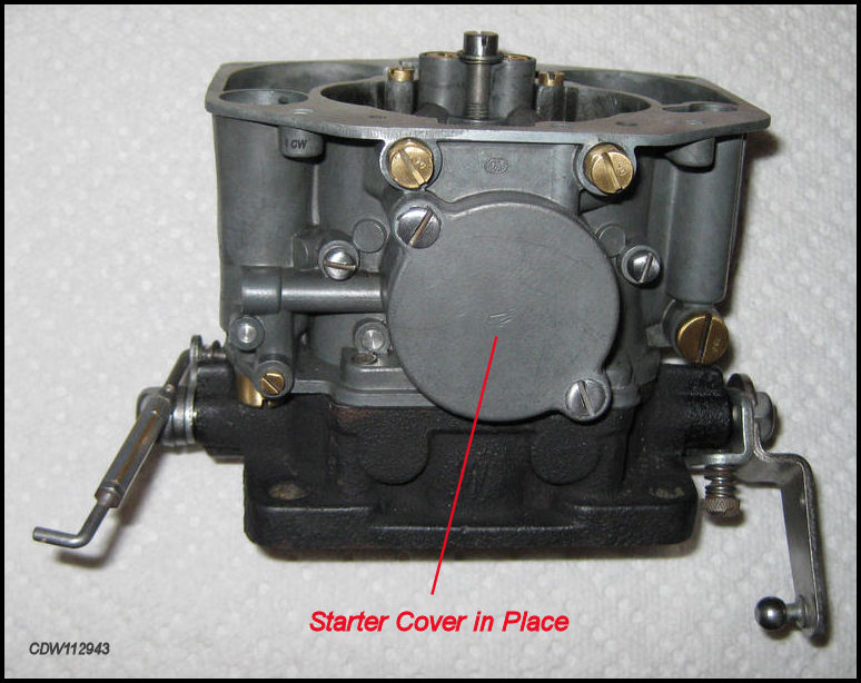
Replacing the Starter Cover.
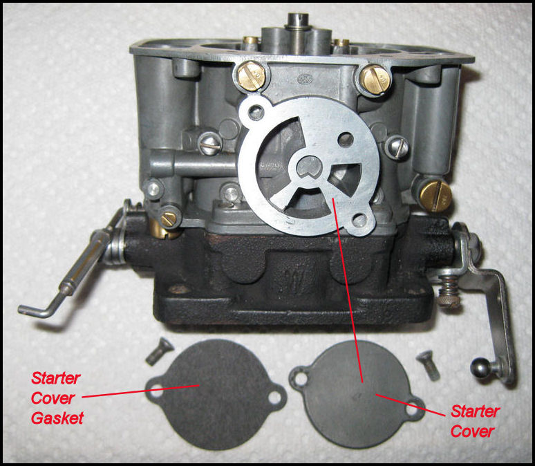 |
A new Starter Cover Gasket should come with the rebuild kit. |
 |
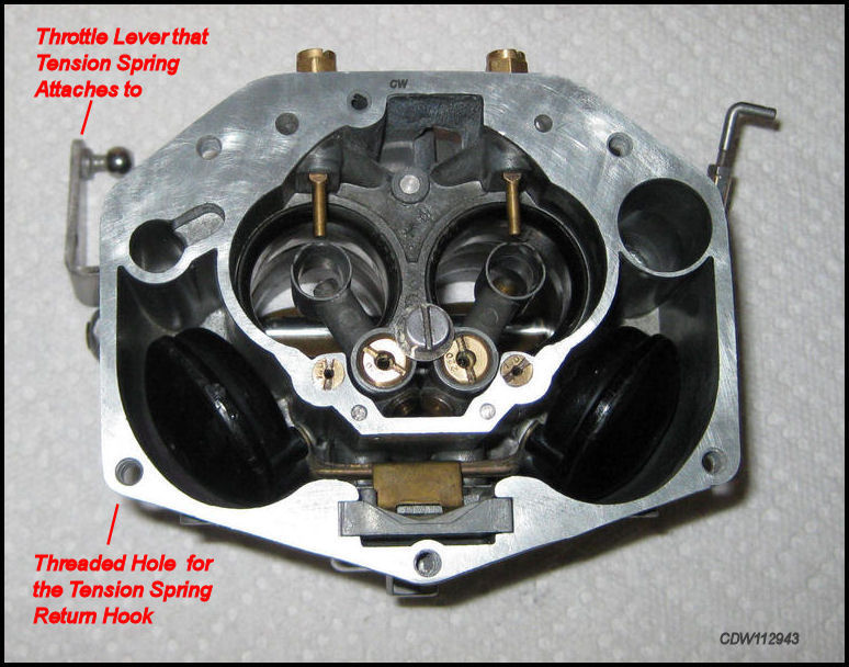
Checking the Threaded Hole on top of the Carb Body for the Spring Return Hook.
 |
 |
The Threaded Hole in the
Carb Top for the Carb
Top Screw that holds the Tension Spring
Return Hook should be carefully checked because
it is often worn or stripped due to the extra
tension from the Tension Return Spring and
the fact that the Carb Top Screw is the
same size as the other four Carb Top Screws.
The extra load on that particular
Carb Top Screw can, over time, strip the
threads. If the threads are stripped,
now is the best time to to do a fix.
No fix
or a poor fix may result
in leaks from between the Carb Top and the
Carb Body on that side of the
carburetor. Re-tapping the hole
and using a slightly longer screw is one
possible fix. Helicoils are another fix but may be more problematic. One
parts supplier can supply a longer top cover screw for this
situation.
Reassembly of Carburetor Top and Carburetor Body.
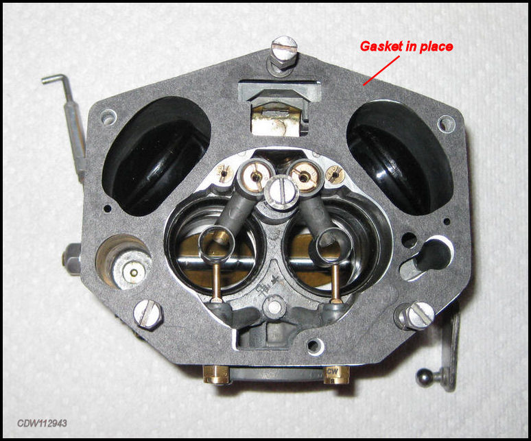
|
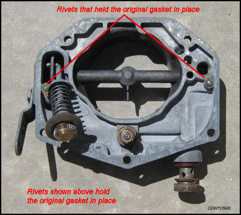
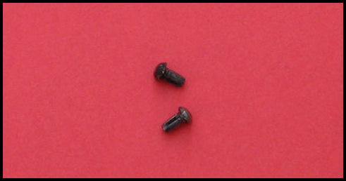
|
Rivets hold original gasket in place. Some say they are not necessary in a rebuild. |
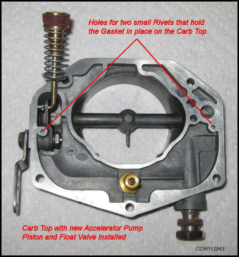
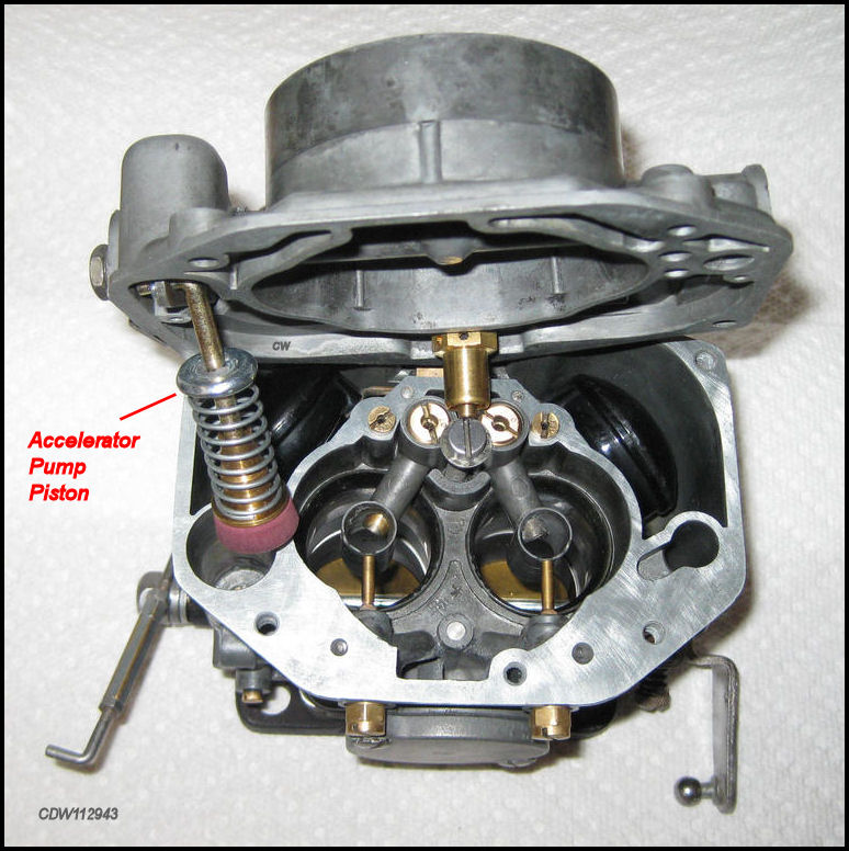
|
Carb
Top
with new
Accelerator Pump
Piston
and
Float Valve
ready to reassemble.
Notice
the
small |
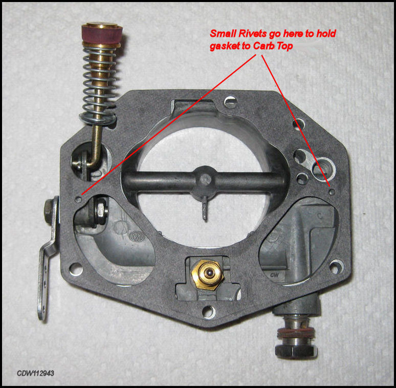
|
Carb
Top with
Gasket. Arrows show
where
two
rivets
hold the
Gasket
to
the Carb
Top. The rivets |
|
Carb Top and Main Carb Body shown without the gasket. |
|
Gasket shown on top of Carburetor Body. |
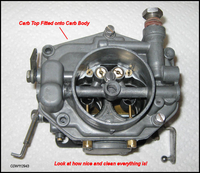
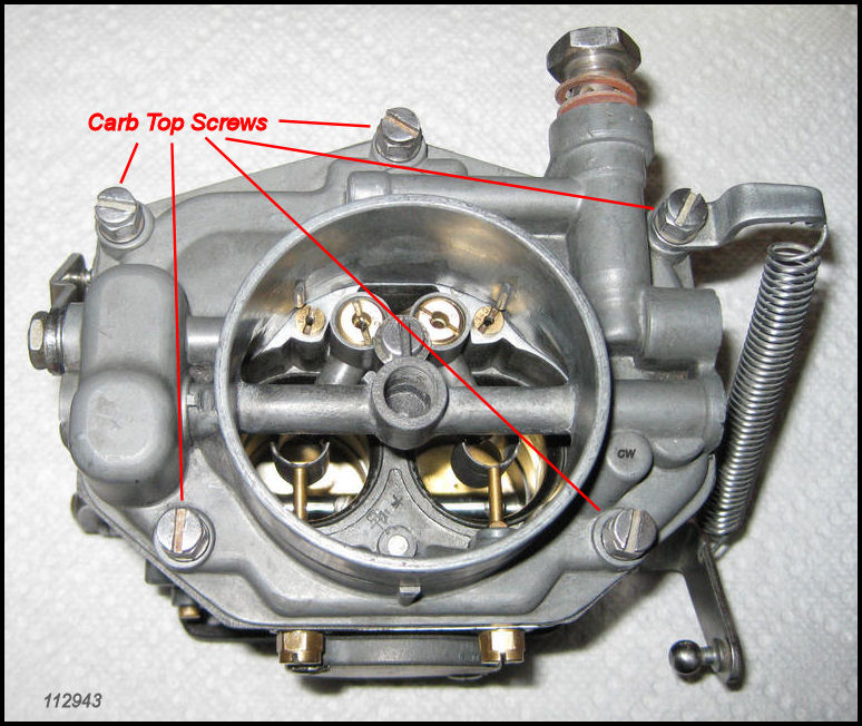
|
|
Use a Nut Driver not a flat blade screw driver to tighten the Carb Top Screws. Don't over tighten! |
Checking the Tension Spring.
There is a specific |
 |
Before
adding the Accelerator Pump Link Rod be sure it such that there are an equal number of threads showing on each end of the rod, in case adjustment is needed later! |
 |
Adjusting your Rebuilt Carburetor!
The fun starts NOW! Now that you have rebuilt your carburetor, you have to put it back on the engine and get it properly adjusted! Make no mistake adjusting your rebuilt Zenith 32 NDIX Carburetor is the hardest part of the process once you have completed the rebuild of your carburetor. Adjusting your carburetor is an art and is best accomplished by trial and error. You start at a particular point and you adjust for the best results. Perhaps the most important prerequisite to adjusting of your newly rebuilt Zenith carburetor is having a properly tuned and adjusted engine. This means proper ignition timing with new parts as required and proper valve timing with the valve clearances set to factory specifications.
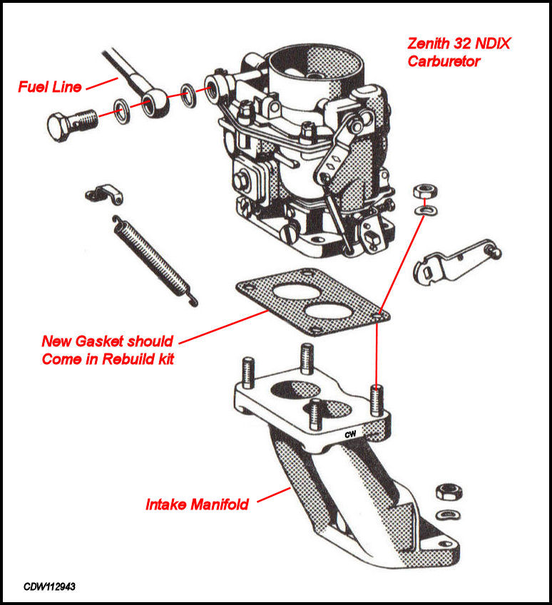
Installing your Rebuilt Carburetor.
When you're ready to install your rebuilt carburetor, make sure the Accelerator Pump Links, Throttle Lever and Return Spring are already on the carburetor. Drop the new gasket from your rebuild kit onto the Intake Manifold, and then place the carburetor on top. Secure it in place with the four 12mm hex nuts with lock washers. When tightening these hex nuts, be sure to keep the wrench away from contacting and bending or breaking the Idle Mixture Screws. Removing a broken Idle Mixture Screw can be a real hassle. Connect the Fuel Line using the appropriate two fiber washers as shown in the line drawing below. The carburetor should now be ready for adjusting.
 |
Adjusting the Float Level.
Adjusting the Float Level can be done with the newly rebuilt carburetor on the bench, or on a motor that has been removed from the car, or on the motor still installed in the car. The level of difficulty varies depending on what method you use. Access to the carburetor and getting fuel into the carburetor are two issues. If you're adjusting the Float Level with your carburetor sitting on the bench, obviously access is not going to be a problem. The problem will be getting fuel into the Float Bowls to take a measurement. The same applies to a carburetor that is already installed on a motor after it's been removed from the car. The problem is reversed if you're working on a carburetor while the motor is still in the car. Access to the carburetor becomes the problem, and getting fuel into the float bowls is not.
 |
Here are two methods that can be used
to determine the Float Level and which method
you use will be determined by whether the carburetor is
on the bench, mounted on
a motor out of the car, or on the
motor still in the car.
If you are measuring the float level with the carburetors
properly mounted in the car, you can use the first
method which employs a "ruler" like measuring
device such as the paper float level gauge that comes with most
rebuild kits. This is fairly easy to do when the carburetor is mounted and
in the car with the fuel line connected. Start the engine and allow the fuel
pump to fill the Float Bowls. Using the
starter only to turn over the engine will also fill the
Float Bowls. Disconnect the fuel line and
remove the carburetor top. With the Floats
in place, measure the distance from the
top of the Float Chamber to the level or
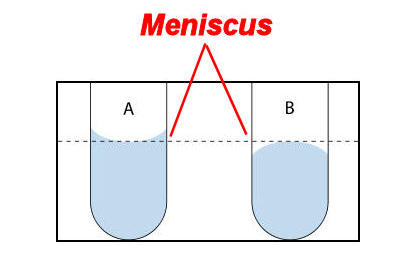
the "meniscus of the fuel".
The meniscus is the
curve in the upper surface of a liquid close to the surface of a container
or in this case the walls of the Float Chamber,
caused by surface tension. The following
diagram shows the meniscus of a fluid. The
meniscus can be either convex or concave
depending on the fluid. For gasoline, the
meniscus is concave as shown below.
 |
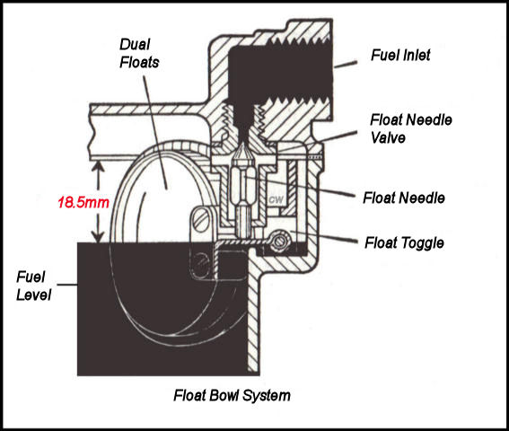
Below you can see the specific distance that is
to be measured, which is the distance from the top of the
Float Chamber to the
meniscus of the fuel. This distance should
be
18.5mm.
 |
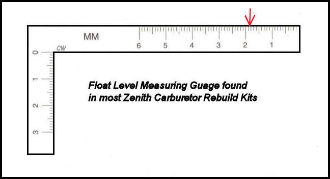 |
Above is a picture of the Float Level Gauge provided in most rebuild kits. |
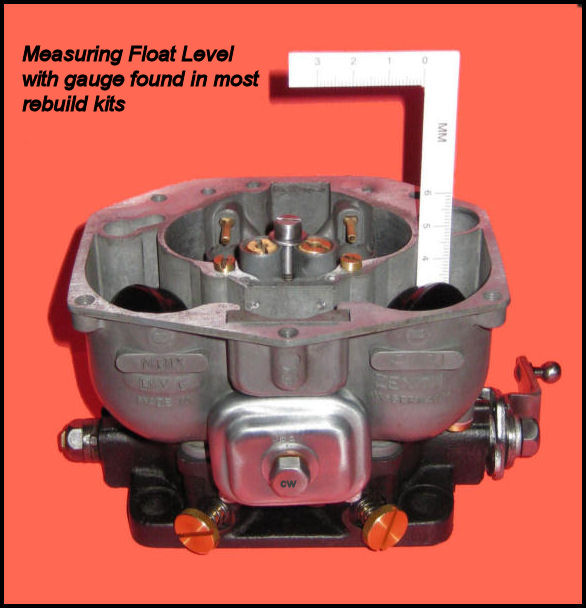 |
Measuring the Float Level using the
paper gauge found in most rebuild kits. |
The second method utilizes
Factory Tool F77 which attaches to the
carburetor below and to the right of the Starter
Cover. This doesn't work very well with the
carburetors installed on the motor and the motor still in the car,
particularly the driver's side carburetor,
as the plug for the tool faces the motor and there's very little room
to screw in the Factory Tool.
Try mounting and reading this gauge on the driver's
side carburetor! It is also problematic to use the
Factory Tool when the carburetors are on
the bench as getting fuel in the Float Bowl
then becomes the problem.
 |
| The Factory Workshop Manuals state the following: |
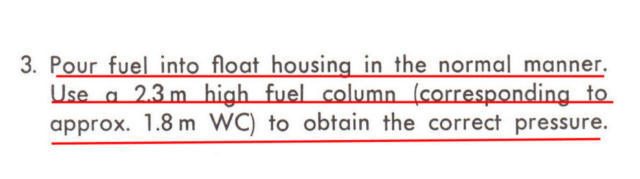 |
"Normal manner"
means having
a 7.5 foot
high vertical length of metal
or rubber fuel line situated close to the carburetor filled with
gas. The purpose for this setup is to
have the proper fuel pressure at the carburetor.
This method is not very practical for the average enthusiast, as there is the very real problem of putting the gas in this vertical fuel line to begin with, and the resulting problems if this rig starts leaking. Realistically speaking, only a properly set up rebuild shop would likely have this kind of arrangement. And if you decide to try the factory method with the 7.5 feet of vertical fuel line nearby, but sure to leave the garage door open and have a fire extinguisher available!
| The manuals go on to say: |
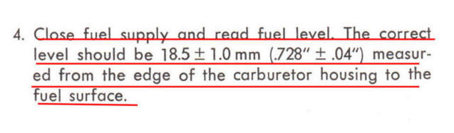 |
The Factory Tool F77 has a clear plastic
tube that is calibrated between 15.0mm and 20.0mm. After the fuel has been
put into the carburetor, the Float Level will
be shown in the clear plastic tube. Again, the factory specification for
the float level is 18.5 +/- 1.0mm (.728" +/-
0.4").
Adjusting the Float Level is accomplished by changing the number and/or size of the washers between the Float Valve and the Carb Top.
 |
Since your rebuild probably included installing the new
Float Valve that came with the rebuild kit,
some would suggest using the same size washer
that you had before the rebuild as a starting
point for measuring the Float
Level. If that setup does not result in the
18.5mm +/- 1.0mm (.728" +/- .01") factory
recommended level, then some adjustments are in order.
Ron LaDow, a well known Zenith carburetor expert, said the following about the Float Valve adjustments in his article titled: "Zenith 32mm NDIX Carburetor Tuning!"
"Adjustments are made by changing the washers where the float valve screws into the carb top. Typically the one 1mm washer supplied in the gasket set won't be enough; start with some stack of washers approximating .06" (1.5mm). The ratio between the float valve washer and float level is ~1:4, such that a .04" (1mm) washer will alter the fuel height by .160" (~4mm). Adding washers lowers the level and vice-versa. Add or subtract washers until you get within .04" (1mm) of the spec. Fiber, aluminum, or copper washers will do, but make sure the float valve seats properly with the selected washers installed."
There are a number of factors that can affect the Float Level besides changing the number or thickness of the washers between the Float Valve and the Carb Top, including the thickness of the gasket between the Carb Top and the Carb Body. The thicker the gasket, the further away the tip of the Float Valve is from the Float Mechanism, and the higher the Float Level. Also over-tightening of the Float Valve can compress the washer causing the Float Level to be higher. Other factors that can affect Float Level are an uneven surface where the tip of the Float Valve touches the Float Mechanism, and certain "oddball" Float Valves that may be available that are of a slightly different size.
Checking/Adjusting the Fuel Injection Ratio.
The Accelerator Pump is actuated when your foot hits the Accelerator Pedal. The linkage forces down a piston in the Accelerator Pump which forces a squirt of gas through the Pump Suction Valve into the Pump Chamber. The down stroke of the piston forces the fuel through the Pump Pressure Valve up to the Pump Jets and through the Injection Nozzles into the carburetor throats. On the up stroke of the Pump Piston, the Pump Suction Valve opens to allow fuel into the Pump Chamber. On the next down stroke of the Pump Piston, the Pump Pressure Valve allows the fuel to exit towards the Pump Jets and Injection Nozzles.
Setting the right amount of fuel that is squirted through the Pump Jets and Injection Nozzles into the carburetor throats is called setting the fuel injection ratio. The factory recommended amount is approximately 0.2cc to 0.3cc of fuel for TWO (2) stokes of the accelerator pump per injection nozzle for optimum engine performance. Less injection quantity is called for when it's warm and more when it's cold.
 |
Actually trying to measure the amount of fuel ejected through the
Pump Jets and
Injection Nozzles can be
problematic. It is physically difficult to
get a measuring device down into the carburetor and close to the
Injection Nozzles to make the measurement.
Factory Tool P25a is a glass tube with level
markings that is placed down into the carburetor by way of a piece of wire
to measure the ejected fuel coming out of the Injection
Nozzles. However, there may be problems with using this tool with
certain Venturi sizes as it may not fit.
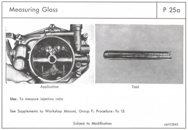 |
Factory Tool P25a as shown in the Factory B/C Workshop Manual. |
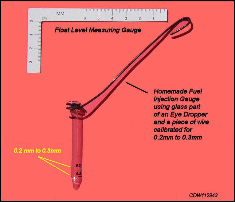 |
Above is a home made Fuel Injection Gauge. |
 |
Fuel Injection Gauge shown down under the Injection Nozzle. |
Most carburetor builders, if they don't already have
Factory Tool P25a, make their own tool to
measure fuel injection volume out of a plastic soda straw or the glass portion
of an eye dropper and a piece of wire. The gauge is calibrated for
0.2cc to 0.3cc. Once calibrated for
0.2cc to 0.3cc, a piece of thin wire is attached
to drop the tool down under the
Injection Nozzles to measure the amount
of fuel injected.
Whatever you use, it should be calibrated in cc's and it should not be much larger in diameter than ¼ inch otherwise it won't fit down into the carburetor and under the Injection Nozzles. Remember 0.2cc to 0.3cc's! A perfect tool would be the glass portion of an eye dropper, not more than about 2 inches long, with the rubber part removed and the small end sealed off. A small piece of wire around the top of the tool will allow it to be lowered down into the carburetor. Remember that the holes in the Injection Nozzles face straight down, so it's necessary to get the top of the tool under these holes to catch the injected fuel.
Adjusting the injection ratio is accomplished by adjusting the Accelerator Pump Link, which has two small lock nuts on either end of the adjusting nut. Loosen the two lock nuts and screw the center adjusting nut either clockwise to decrease the amount of fuel injected, and counter clockwise to increase the fuel injected. After your initial measurement of fuel injected, adjust the length of the Accelerator Pump Link as described above and do another measurement. Keep doing the measurements until the amount of fuel injected is correct. Once the injection amount is 0.2cc's to 0.3cc's for TWO (2) strokes of the Accelerator Pump, stop and tighten the two lock nuts.
 |
 |
Setting the Idle Mixture.
 |
The idle mixture adjustment is accomplished
by adjusting the Idle Mixture Screws located
on the bottom of the jet cover face of the carburetor. This is probably the
easiest adjustment to make on a Zenith 32 NDIX
Carburetor. First, remove both Idle Mixture
Screws. Be careful not to lose the little
springs. Either replace them with new Idle
Mixture Screws from the rebuild kit, or make sure they both are
not damaged, and the points of the screws are not scared or bent. Then
carefully screw both
Idle Mixture Screws all
the way in until they seat. You don't want
to dent or bend the tips of the Idle Mixture
Screws when they seat! Then screw both the
Idle Mixture Screws out
1 1/4 to 1 1/2 turns. This will be your starting
point to make the adjustments.
Now start your engine and let it idle a few minutes to warm up to a normal idle speed. Carefully either screw in or screw out each Idle Mixture Screw to obtain the highest idle speed. You can do this by listening to the engine or watching the tachometer. Adjust the Idle Mixture Screws back and forth with each carburetor until maximum idle speed is obtained. Once you have maximized the performance from each carburetor, the next step is to balance the two carburetors so they are both performing at the same level.
Balancing the Carburetors.
Balancing or synchronizing the carburetors means setting them so that the air flow is the same or a close to the same as you can get it, in both carburetors. The theory is very simple; each carburetor serves half or two cylinders of the engine. If both carburetors are providing an equal fuel and air mixture to each side of the engine, the balance will provide maximum power.
First start the engine and let it idle normally. Remove the carburetor linkage from both carburetors. Balancing the carburetors is accomplished by using a flow metering device that measures the flow of air into each carburetor. A Unisyn is one flow metering device commonly used on Zenith carburetors. There are other devices that will accomplish the same thing.
 |
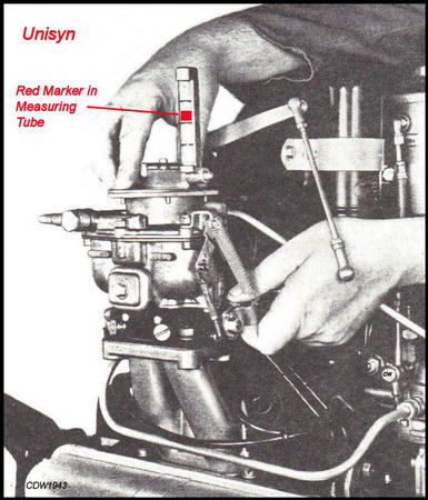 |
The Unisyn is placed on top of the
carburetor centered over the air intake with the engine running. In the center
of the base of the Unisyn is a mechanism
for adjusting the air flow to a measurable level. Open
it up and more air comes in and vice versa. Adjust the air flow
to a level that can be measured in the calibrated glass tube. The little
red marker will move up and down indicating the level of air flow. Once set,
use the Unisyn on both carburetors and
adjust the air flow using the
idle adjustment screw
(NOT the
Idle Mixture Screw!) on the
Throttle Lever. The little
red marker in the glass tube should rise
to the same level for both carburetors. Trial and error are necessary to
get a good balance.
Finished Carburetor..........Some Summary Thoughts!
Everything you have seen done in these pictures was done in my garage with readily available tools and supplies. No outside work was done, no cleaning and no machining! The cleaning was done with carburetor cleaner that came in a gallon sized can with a plastic basket inside so the parts could be dipped into the cleaner in the can. Parts were then washed in tap water. The flat edges of the carburetor look like they were machined. They were not! All it took was 400 grit sandpaper laid on a flat concrete floor. The flat edges were applied face down on the sandpaper and sanded clean.
|
The Jets Cover side of the Carburetor with the Idle Mixture Screws. |
|
The Starter Cover side of the Carburetor with the Pump Jets above and Plug to the right. |
|
"R" stands for "Right". There are Left and Right Carburetors. |
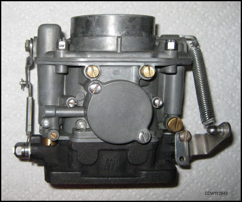
|
Rebuilt Carburetor ready to adjust and put back on the car! |
No parts were replated. All were buffed
on a small buffing wheel to bright metal, including the brass parts. Jets
were cleaned in the carburetor cleaner, and blown out
with compressed air. Thin copper wire and nylon fishing line were
also used to insure no obstructions remained in the jets and valves. A
rebuild kit was purchased from
one of the regular suppliers. It included all
new gaskets, a new accelerator pump piston, two new idle mixture screws,
a new float valve, and a variety of washers. Also included was a part diagram,
which I didn't find particularly helpful. The
rest of the parts were reused.
The variety and sizes of washers caused a momentary problem. It was difficult to determine which washer went where, and the instructions weren't much help. The kit contained fabric washers, aluminum washers, and one copper washer. Some of the washers were of similar size, but not exactly the same, and it was hit or miss figuring out which went where. When installing the washers it is important that they fit properly, not loosely. The above images of the parts in the kit may be of some help determining which washers go where.
Tools used included a slot head screwdriver, an 8mm nut driver, 10mm and 12mm open-end wrenches, a variety of scrubbing brushes, a roll of paper towels, and a small bench grinder/polisher. Supplies include the gallon can of carb cleaner, 400 grit sandpaper, some thin gauge copper wire, and some nylon fishing line. To keep things sorted, a plastic shoe box with a lid, and several glass jars with lids along with several zip-lock plastic bags were very helpful.
Since time was not of the essence, the project was completed over a period of two weeks. Working a few hours here and there and whenever motivated. A Pro could probably do the job in a couple of hours. Speaking of Pros, help was provided by the Pros listed below in the Reference Sources. Special thanks to all those guys who gave great advice and information when there were questions about the rebuild!
After doing this project, and patting myself on the back for taking my time and asking questions when issues arose, the Easy Conclusion is just about anybody can rebuild a Zenith 32 NDIX Carburetor. A couple of recommendations: 1. Take your time, 2. Ask questions, and 3. Take a lot of pictures so you know what it looked like before you started, and how it looked when you finished. Hopefully the pictures in this website will be of some assistance.
Finally, it should be emphasized that some problems with Zenith 32 NDIX Carburetors are best left to EXPERTS! Such issues as problems with float levels, warped surfaces, stripped threads, fuel leaks and more precise tuning may be beyond the average enthusiast's ability to properly fix. Changing jets for more performance or altitude issues can be complicated. It's best to know what you started with if any changes you make don't work. That way you can at least get back to square one. It you get lost along the way, get your friendly 356 Vendor involved!
Charlie White
Scottsdale, Arizona
 |
Comments
regarding the accuracy and completeness if
this website are
welcome!
to:
derwhite@aol.com
![]()
Reference Sources:
Zenith-Carburetor, Dual-downdraught Type 32/36 NDIX, Pallas
Apparate Gesellschat M.B.H.
Rebuilding Zenith 32 NDIX Carburetors, by
Ron LaDow, found at:
Click
for Article
Tuning Zenith 32 NDIX
Carburetors, by Ron LaDow, found
at:
Click
for Article
356 B/C Porsche Factory Workshop Manual
356-A Porsche Factory Workshop Manual
356-B T-5 Porsche Factory Parts Book
356-A Porsche Factory Parts Book
Specs, 3rd English Edition, Information Please, Porsche Factory
Porsche Factory Service Bulletin #4/58
Special THANKS to the following for
invaluable help with this
rebuild project and website!
Ron LaDow
Dick Weiss
Larry Coreth
Richard Shilling
Wes Bender
![]()
"DerWhite's
356
Porsche
Sales
& Technical
Literature......the
Book!"

Size 8.5 x 11 inches,
Hardbound, 356 Pages,
All
Color!
![]() Click
here for more details about
DerWhite's
New Book!
Click
here for more details about
DerWhite's
New Book!
![]()
All of the pictures on this
website were created by this author,
and are Copyrighted! No use of these
pictures
for any purpose will be permitted without the
prior written permission of this author! All
legal rights reserved.
Some pictures on this website have been digitally enhanced for
clarity purposes.
![]()
Reporting on how to rebuild a Zenith 32 NDIX Carburetor for
a Porsche 356!
Research and website creation by:
Charlie
White
Scottsdale, Arizona
USA
derwhite@aol.com
Copyright@2011 DerWhite Productions,
Phoenix, Arizona,
USA
Website initially created
11/11/11.